Toyota Venza: Vsc Off Switch
Components
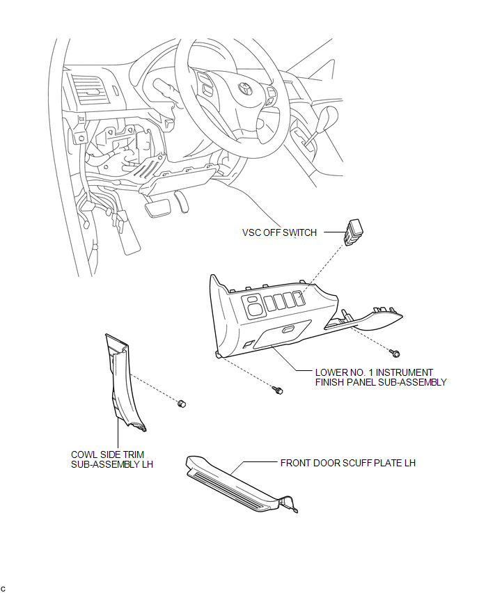
COMPONENTS
ILLUSTRATION
Removal
REMOVAL
PROCEDURE
1. DISCONNECT CABLE FROM NEGATIVE BATTERY TERMINAL
NOTICE:
When disconnecting the cable, some systems need to be initialized after the cable
is reconnected (See page .gif) ).
).
2. REMOVE FRONT DOOR SCUFF PLATE LH
3. REMOVE COWL SIDE TRIM SUB-ASSEMBLY LH
4. REMOVE LOWER NO. 1 INSTRUMENT FINISH PANEL SUB-ASSEMBLY
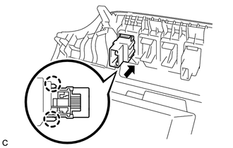
5. REMOVE VSC OFF SWITCH
|
(a) Disengage the 2 claws and remove the VSC OFF switch. |
|
Inspection
INSPECTION
PROCEDURE
1. INSPECT VSC OFF SWITCH
(a) Disconnect the VSC OFF switch connector.
|
(b) Measure the resistance according to the value(s) in the table below. Standard Resistance:
If the value is not as specified, replace the VSC OFF switch. |
|
.png)
Installation
INSTALLATION
PROCEDURE
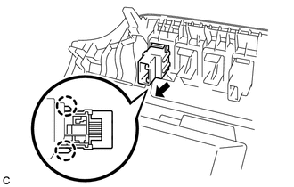
1. INSTALL VSC OFF SWITCH
|
(a) Engage the 2 claws and install the VSC OFF switch. |
|
2. INSTALL LOWER NO. 1 INSTRUMENT FINISH PANEL SUB-ASSEMBLY
.gif)
3. INSTALL COWL SIDE TRIM SUB-ASSEMBLY LH
4. INSTALL FRONT DOOR SCUFF PLATE LH
5. CONNECT CABLE TO NEGATIVE BATTERY TERMINAL
NOTICE:
When disconnecting the cable, some systems need to be initialized after the cable
is reconnected (See page ).
6. CHECK FOR WARNING LIGHT AND INDICATOR LIGHT
HINT:
(See page ).
 TS and CG Terminal Circuit
DESCRIPTION
In the Test Mode (signal check), a malfunction in the speed sensor that cannot
be detected when the vehicle is stopped can be detected while driving.
Transition to the sensor check mod ...

Other materials about Toyota Venza:
BUS IC Communication Malfunction (B1497/97)
DESCRIPTION
The air conditioning harness connects the A/C amplifier and each servo. The A/C
amplifier supplies power and sends operation instructions to each servo through
the air conditioning harness. Each servo sends the damper position information to
...
Power Source Control ECU Malfunction (B2782)
DESCRIPTION
The power management control ECU controls the power supply to activate the steering
lock motor. This prevents the steering wheel from being locked while the vehicle
is moving.
DTC No.
DTC Detecting Condition
T ...
Seat belts
Make sure that all occupants are wearing their seat belts before driving the
vehicle.
- Correct use of the seat belts
1. Extend the shoulder belt so that it comes fully over the shoulder, but does
not come into contact with the neck or slide off ...

0.1493