Toyota Venza: Transmission Control Switch Circuit
DESCRIPTION
When the shift lever is in S and it is moved toward "-" or "+", it is possible to select different shift ranges (1st through 6th ranges).
Moving the shift lever toward "+" increases the shift range by one, and moving the shift lever toward "-" decreases the shift range by one.
WIRING DIAGRAM
.png)
PROCEDURE
|
1. |
CHECK HARNESS AND CONNECTOR (BATTERY - TRANSMISSION CONTROL SWITCH) |
|
(a) Disconnect the transmission control switch connector of shift lock control unit assembly. |
|
(b) Measure the voltage according to the value(s) in the table below.
Standard Voltage:
|
Tester Connection |
Condition |
Specified Condition |
|---|---|---|
|
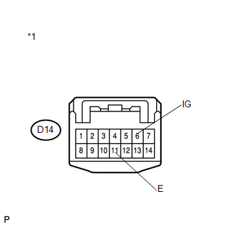
D14-6 (IG) - Body ground or other terminals |
Ignition switch ON |
11 to 14 V |
|
Ignition switch off |
Below 1 V |
|
*1 |
Front view of wire harness connector (to Transmission Control Switch) |
| NG | .gif) |
REPAIR OR REPLACE HARNESS OR CONNECTOR |
|
.gif)
|
2. |
CHECK HARNESS AND CONNECTOR (TRANSMISSION CONTROL SWITCH - BODY GROUND) |
|
(a) Measure the resistance according to the value(s) in the table below. Standard Resistance:
|
|
| NG | |
REPAIR OR REPLACE HARNESS OR CONNECTOR |
|
|
3. |
INSPECT SHIFT LOCK CONTROL UNIT ASSEMBLY (TRANSMISSION CONTROL SWITCH) |
|
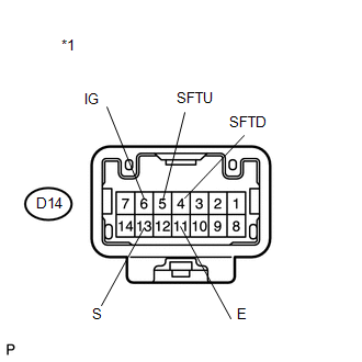
(a) Measure the resistance between each terminal of the transmission control switch when the shift lever is moved to each position. Standard Resistance:
|
|
| NG | |
REPLACE SHIFT LOCK CONTROL UNIT ASSEMBLY (TRANSMISSION CONTROL SWITCH) |
|
|
4. |
CHECK HARNESS AND CONNECTOR (TRANSMISSION CONTROL SWITCH - ECM) |
(a) Connect the transmission control switch connector.
(b) Disconnect the ECM connector.
(c) Turn the ignition switch to ON.
(d) Measure the voltage according to the value(s) in the table below.
Standard Voltage:
|
Tester Connection |
Condition |
Specified Condition |
|---|---|---|
|
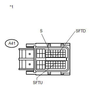
A41-25 (S) - Body ground or other terminals |
|
11 to 14 V |
|
A41-25 (S) - Body ground or other terminals |
|
Below 1 V |
|
*1 |
Front view of wire harness connector (to ECM) |
(e) Turn the ignition switch off.
(f) Disconnect the spiral cable connector.
(g) Measure the resistance according to the value(s) in the table below.
Standard Resistance:
|
Tester Connection |
Condition |
Specified Condition |
|---|---|---|
|
A41-38 (SFTU) - Body ground or other terminals |
Shift lever held in "+" (Up-shift) |
Below 1 Ω |
|
Shift lever not held in "+" |
10 kΩ or higher |
|
|
A41-27 (SFTD) - Body ground or other terminals |
Shift lever held in "-" (Down-shift) |
Below 1 Ω |
|
Shift lever not held in "-" |
10 kΩ or higher |
| OK | |
PROCEED TO NEXT SUSPECTED AREA SHOWN IN PROBLEM SYMPTOMS TABLE |
| NG | |
REPAIR OR REPLACE HARNESS OR CONNECTOR |
 System Voltage (P0560)
DESCRIPTION
The battery supplies electricity to the TCM even when the ignition switch is
off. This power allows the TCM to store data such as DTC history and freeze frame
data. If the battery vol ...
 ECU Power Source Circuit
DESCRIPTION
When the ignition switch is turned to ON, voltage from the ECM's MREL terminal
is applied to the EFI MAIN relay. This causes the contacts of the EFI MAIN relay
to close, which sup ...
Other materials about Toyota Venza:
Power Mirror cannot be Adjusted with Power Mirror Switch
SYSTEM DESCRIPTION
The main body ECU (driver side junction block assembly) detects the mirror adjust
switch status and sends the signal to the outer mirror control ECU assembly via
CAN communication. On receiving the signal, each outer mirror control ECU ...
System Description
SYSTEM DESCRIPTION
1. FRONT POWER SEAT CONTROL SYSTEM DESCRIPTION
The driver seat is equipped with slide, reclining, lifter, front vertical,
and lumbar support adjustment functions.
The memory call function uses the key ID code of the key to m ...
Customize Parameters
CUSTOMIZE PARAMETERS
HINT:
The following items can be customized.
NOTICE:
After confirming whether the items requested by the customer are applicable
or not for customization, perform customizing operations.
Be sure to record the current se ...

0.1139