Toyota Venza: ECU Power Source Circuit
DESCRIPTION
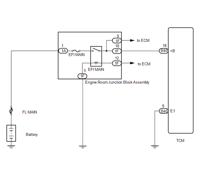
When the ignition switch is turned to ON, voltage from the ECM's MREL terminal is applied to the EFI MAIN relay. This causes the contacts of the EFI MAIN relay to close, which supplies power to terminal +B of the TCM.
WIRING DIAGRAM
PROCEDURE
|
1. |
CHECK HARNESS AND CONNECTOR (TCM - BODY GROUND) |
|
(a) Turn the ignition switch off. |
|
(b) Disconnect the TCM connectors.
(c) Measure the resistance according to the value(s) in the table below.
Standard Resistance:
|
Tester Connection |
Condition |
Specified Condition |
|---|---|---|
|
B40-8 (E1) - Body ground |
Always |
Below 1 Ω |
|
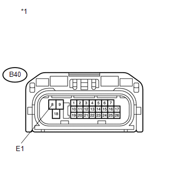
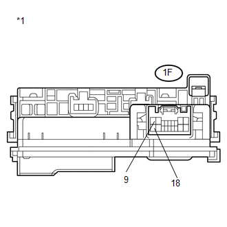
*1 |
Front view of wire harness connector (to TCM) |
| NG | .gif) |
REPAIR OR REPLACE HARNESS OR CONNECTOR |
|
.gif)
|
2. |
INSPECT ECU TERMINAL VOLTAGE (+B TERMINAL) |
|
(a) Disconnect the TCM connectors. |
|
(b) Turn the ignition switch to ON.
(c) Measure the voltage according to the value(s) in the table below.
Standard Voltage:
|
Tester Connection |
Switch Condition |
Specified Condition |
|---|---|---|
|
B40-18 (+B) - Body ground |
Ignition switch ON |
11 to 14 V |
|
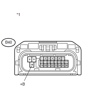
*1 |
Front view of wire harness connector (to TCM) |
| OK | |
PROCEED TO NEXT SUSPECTED AREA SHOWN IN PROBLEM SYMPTOMS TABLE |
|
|
3. |
CHECK HARNESS AND CONNECTOR (TCM - ENGINE ROOM JUNCTION BLOCK ASSEMBLY) |
(a) Turn the ignition switch off.
(b) Disconnect the TCM connector.
(c) Remove the engine room junction block assembly from the engine room relay block.
(d) Measure the resistance according to the value(s) in the table below.
Standard Resistance (Check for Open):
|
Tester Connection |
Condition |
Specified Condition |
|---|---|---|
|
B40-18 (+B) - 1F-18 (+B) |
Always |
Below 1 Ω |
Standard Resistance (Check for Short):
|
Tester Connection |
Condition |
Specified Condition |
|---|---|---|
|
B40-18 (+B) or 1F-18 (+B) - Body ground |
Always |
10 kΩ or higher |
|
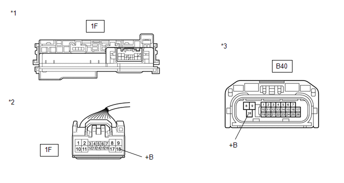
*1 |
Engine Room Junction Block Assembly |
|
*2 |
Front view of wire harness connector (to Engine Room Junction Block Assembly) |
|
*3 |
Front view of wire harness connector (to TCM) |
| NG | |
REPAIR OR REPLACE HARNESS OR CONNECTOR |
|
|
4. |
INSPECT ENGINE ROOM JUNCTION BLOCK ASSEMBLY |
|
(a) Measure the resistance according to the value(s) in the table below. Standard Resistance:
|
|
| OK | |
GO TO ECM POWER SOURCE CIRCUIT (ENGINE CONTROL SYSTEM / SFI SYSTEM) |
| NG | |
REPLACE ENGINE ROOM JUNCTION BLOCK ASSEMBLY |
 Transmission Control Switch Circuit
DESCRIPTION
When the shift lever is in S and it is moved toward "-" or "+", it is possible
to select different shift ranges (1st through 6th ranges).
Moving the shift lever tow ...

Other materials about Toyota Venza:
Garage Door Opener Switch
Components
COMPONENTS
ILLUSTRATION
Removal
REMOVAL
PROCEDURE
1. REMOVE ROOF CONSOLE BOX ASSEMBLY (GARAGE DOOR OPENER SWITCH)
(a) Using a moulding remover, disengage the 2 claws and 2 clips.
Text in Illustration
*1 ...
Precaution
PRECAUTION
1. PRECAUTION FOR DISCONNECTING THE BATTERY CABLE
NOTICE:
When disconnecting the cable from the negative (-) battery terminal, initialize
the following systems after the cable is reconnected:
System
See Procedure
...
Differential System
Precaution
PRECAUTION
Before disassembly, clean the outside of the differential assembly and
remove any sand or mud to prevent it from entering the inside of the assembly
during disassembly and installation.
When removing an installed pa ...

0.1578