Toyota Venza: Differential Oil Seal
Components
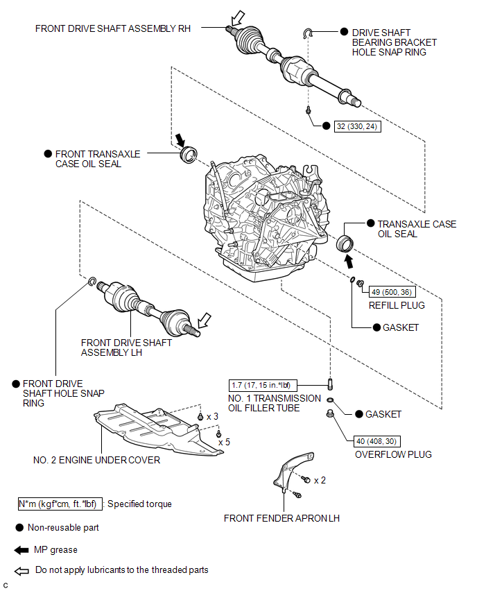
COMPONENTS
ILLUSTRATION
Replacement
REPLACEMENT
PROCEDURE
1. DRAIN AUTOMATIC TRANSAXLE FLUID
(a) Remove the No. 2 engine under cover and front fender apron LH.
|
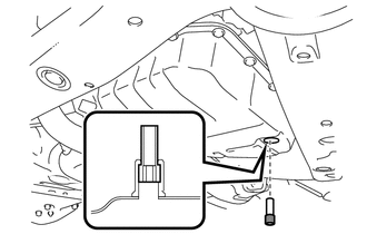
(b) Using a 6 mm socket hexagon wrench, remove the overflow plug and gasket from the automatic transaxle. |
|
.png)
|
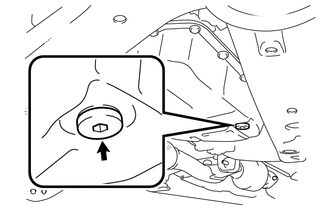
(c) Remove the refill plug and gasket from the automatic transaxle. |
|
.png)
|
(d) Using a 6 mm socket hexagon wrench, remove the No. 1 transmission oil filler tube from the automatic transaxle. |
|
(e) Drain automatic transaxle fluid from the automatic transaxle.
|
(f) Using a 6 mm socket hexagon wrench, install the No. 1 transmission oil filler tube to the automatic transaxle. Torque: 1.7 N·m {17 kgf·cm, 15 in·lbf} |
|
|
(g) Using a 6 mm socket hexagon wrench, install a new gasket and the overflow plug to the automatic transaxle. Torque: 40 N·m {408 kgf·cm, 30 ft·lbf} |
|
|
(h) Install a new gasket and the refill plug to the automatic transaxle. Torque: 49 N·m {500 kgf·cm, 36 ft·lbf} |
|
2. REMOVE FRONT DRIVE SHAFT ASSEMBLY
HINT:
See page .gif)
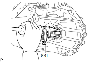
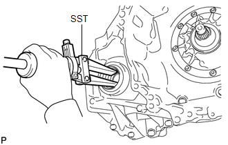
3. REMOVE TRANSAXLE CASE OIL SEAL
|
(a) Using SST, tap out the transaxle case oil seal. SST: 09308-00010 |
|
4. REMOVE FRONT TRANSAXLE CASE OIL SEAL
|
(a) Using SST, tap out the front transaxle case oil seal. SST: 09308-00010 |
|
5. INSTALL TRANSAXLE CASE OIL SEAL
|
(a) Using SST and a hammer, tap in a new transaxle case oil seal. SST: 09316-10010 SST: 09950-70010 09951-07100 Oil seal driven in depth: -0.5 to 0.5 mm (-0.0197 to 0.0197 in.) NOTICE: Check that the oil seal is installed in the correct direction. |
|
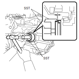
(b) Coat the lip of the transaxle case oil seal with MP grease.
6. INSTALL FRONT TRANSAXLE CASE OIL SEAL
|
(a) Using SST and a hammer, tap in a new front transaxle case oil seal. SST: 09316-60011 09316-00011 Oil seal driven in depth: -0.5 to 0.5 mm (-0.0197 to 0.0197 in.) NOTICE: Check that the oil seal is installed in the correct direction. |
|
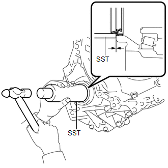
(b) Coat the lip of the front transaxle case oil seal with MP grease.
7. INSTALL FRONT DRIVE SHAFT ASSEMBLY
HINT:
See page
8. ADD AUTOMATIC TRANSAXLE FLUID
HINT:
See page
 Reassembly
REASSEMBLY
PROCEDURE
1. INSTALL FRONT DIFFERENTIAL CASE REAR TAPERED ROLLER BEARING
(a) Using SST and a press, install a new front differential case rear
tapered roller bearing (inne ...
 Oil Pump
...
Other materials about Toyota Venza:
System Description
SYSTEM DESCRIPTION
1. TOUCH SWITCH OUTLINE
(a) Touch switches are touch-sensitive (interactive) switches operated by touching
the screen. When a switch is pressed, the outer film bends in to contact the inner
glass at the pressed position. By doing this, ...
Stereo Component Amplifier Malfunction (B15A3)
DESCRIPTION
This DTC is stored when a malfunction occurs in the stereo component amplifier
assembly.
DTC No.
DTC Detection Condition
Trouble Area
B15A3
When any of the following conditions is met ...
How To Proceed With Troubleshooting
CAUTION / NOTICE / HINT
HINT:
Use the following procedure to troubleshoot the navigation system.
*: Use the Techstream.
PROCEDURE
1.
VEHICLE BROUGHT TO WORKSHOP
NEXT
...

0.1128