Toyota Venza: System Diagram
SYSTEM DIAGRAM
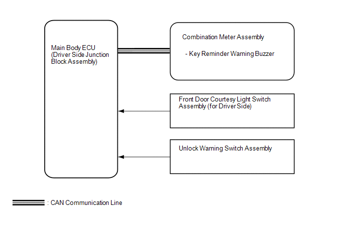 Communication Table
|
Sender |
Receiver |
Signal |
Communication Method |
|---|---|---|---|
|
Main Body ECU (Driver Side Junction Block Assembly) |
Combination Meter Assembly |
Driver side door courtesy light switch signal |
CAN |
|
Main Body ECU (Driver Side Junction Block Assembly) |
Combination Meter Assembly |
Unlock warning switch signal |
CAN |
 Parts Location
PARTS LOCATION
ILLUSTRATION
...
 System Description
SYSTEM DESCRIPTION
1. KEY REMINDER WARNING SYSTEM DESCRIPTION
(a) When the driver side door is opened with the key in ACC or LOCK, this system
causes a buzzer to sound in order to warn the driver ...
Other materials about Toyota Venza:
Components
COMPONENTS
ILLUSTRATION
ILLUSTRATION
ILLUSTRATION
ILLUSTRATION
ILLUSTRATION
...
Precaution
PRECAUTION
1. BEFORE WORKING ON FUEL SYSTEM
(a) When disconnecting a fuel line, fuel will splash. So observe the following
precautions:
(1) Do not smoke or work near fire when handling the fuel system.
(2) Keep gasoline away from rubber or leather parts. ...
System Description
SYSTEM DESCRIPTION
1. FRONT POWER SEAT CONTROL SYSTEM DESCRIPTION
The driver seat is equipped with slide, reclining, lifter, front vertical and
lumbar support adjustment functions.
2. FUNCTION OF MAIN COMPONENTS
The following functions are available:
...

0.1196