Toyota Venza: Replacement
REPLACEMENT
PROCEDURE
1. REMOVE CENTER EXHAUST PIPE ASSEMBLY
(a) Remove the center exhaust pipe assembly.
HINT:
Refer to the instructions for Removal of the exhaust pipe (See page
.gif) for 2GR-FE,
for 2GR-FE,
for 1AR-FE).
2. REMOVE PROPELLER WITH CENTER BEARING SHAFT ASSEMBLY
3. DRAIN DIFFERENTIAL OIL
|
(a) Using a 10 mm hexagon wrench, remove the rear differential carrier cover plug and gasket. |
|
.png)
|
(b) Using a 10 mm hexagon wrench, remove the rear differential drain plug and gasket to drain the differential oil. |
|
.png)
(c) Using a 10 mm hexagon wrench, install a new gasket and the rear differential drain plug.
Torque:
39 N·m {398 kgf·cm, 29 ft·lbf}
|
(d) Using a 10 mm hexagon wrench, temporarily install the rear differential carrier cover plug. HINT: Add differential oil before installing a new gasket and fully tightening the rear differential carrier cover plug. |
|
4. REMOVE ELECTRO MAGNETIC CONTROL COUPLING SUB-ASSEMBLY
|
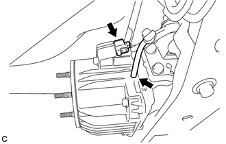
(a) Disconnect the electro magnetic control coupling sub-assembly connector and vacuum hose. NOTICE: Do not damage the electro magnetic control coupling wire harness. |
|
|
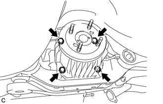
(b) Remove the 4 bolts. |
|
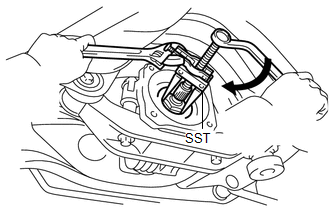
(c) Using a brass bar and a hammer, tap the electro magnetic control coupling sub-assembly to remove the electro magnetic control coupling sub-assembly from the rear differential carrier assembly.
NOTICE:
Do not drop the electro magnetic control coupling sub-assembly.
5. REMOVE TRANSMISSION COUPLING CONICAL SPRING WASHER
|
(a) Remove the transmission coupling conical spring washer from the rear differential carrier assembly. Text in Illustration
|
|
.png)
6. REMOVE TRANSMISSION COUPLING SPACER
|
(a) Remove the transmission coupling spacer from the rear differential carrier assembly. Text in Illustration
|
|
.png)
7. REMOVE DIAPHRAGM OIL SEAL
|
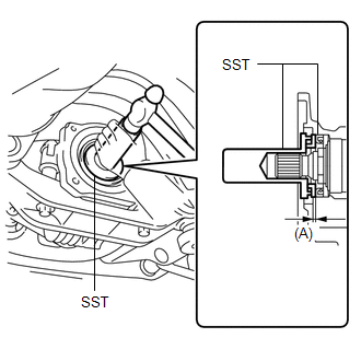
(a) Using SST, remove the diaphragm oil seal from the rear differential carrier assembly. SST: 09308-10010 |
|
8. INSTALL DIAPHRAGM OIL SEAL
|
(a) Using SST and a hammer, install a new diaphragm oil seal into the rear differential carrier assembly. SST: 09506-35010 SST: 09554-22010 Oil seal driven in depth (A): 0.7 to 1.3 mm (0.0276 to 0.0511 in.) |
|
9. INSTALL TRANSMISSION COUPLING SPACER
|
(a) Install the transmission coupling spacer to the rear differential carrier assembly. Text in Illustration
NOTICE: Keep the transmission coupling spacer free of oil and foreign matter. |
|
10. INSTALL TRANSMISSION COUPLING CONICAL SPRING WASHER
|
(a) Install the transmission coupling conical spring washer to the rear differential carrier assembly as shown in the illustration. Text in Illustration
NOTICE: Keep the transmission coupling conical spring washer free of oil and foreign matter. |
|
11. INSTALL ELECTRO MAGNETIC CONTROL COUPLING SUB-ASSEMBLY
(a) Using a scraper and wire brush, remove the seal packing from the rear differential carrier assembly and electro magnetic control coupling sub-assembly.
NOTICE:
- Do not damage the contact surface.
- Be sure to completely remove all seal packing from the rear differential carrier assembly and electro magnetic control coupling sub-assembly.
- Do not allow the removed seal packing to enter the rear differential carrier assembly and electro magnetic control coupling sub-assembly.
(b) Using a non-residue solvent, remove grease and oil from the contact surfaces of the rear differential carrier assembly and the electro magnetic control coupling sub-assembly.
NOTICE:
Do not damage the contact surface.
|
(c) Apply seal packing to the areas indicated in the illustration of the rear differential carrier assembly. Text in Illustration
Seal packing: Toyota Genuine Seal Packing 1281, Three Bond 1281 or equivalent NOTICE:
|
|
.png)
|
(d) Install the electro magnetic control coupling sub-assembly with the 4 bolts. Torque: 20 N·m {200 kgf·cm, 14 ft·lbf} NOTICE:
|
|
|
(e) Connect the electro magnetic control coupling sub-assembly connector and vacuum hose. NOTICE: Do not damage the electro magnetic control coupling wire harness. |
|
12. ADD DIFFERENTIAL OIL
|
(a) Remove the rear differential carrier cover plug. |
|
(b) Add differential oil (See page ).
13. INSPECT DIFFERENTIAL OIL
14. INSTALL REAR DIFFERENTIAL CARRIER COVER PLUG
15. INSPECT FOR DIFFERENTIAL OIL LEAK
16. TEMPORARILY TIGHTEN PROPELLER WITH CENTER BEARING SHAFT ASSEMBLY
17. FULLY TIGHTEN PROPELLER WITH CENTER BEARING SHAFT ASSEMBLY
18. INSTALL CENTER EXHAUST PIPE ASSEMBLY
(a) Install the center exhaust pipe assembly.
HINT:
Refer to the instructions for Installation of the exhaust pipe (See page
for 2GR-FE,
for 1AR-FE).
19. INSPECT AND ADJUST TRANSFER OIL
(a) Inspect and adjust transfer oil (See page
).
20. INSPECT FOR TRANSFER OIL LEAK
 Components
COMPONENTS
ILLUSTRATION
ILLUSTRATION
...

Other materials about Toyota Venza:
Transmission Range Sensor Circuit Malfunction (PRNDL Input) (P0705)
DESCRIPTION
The park/neutral position switch assembly detects the shift lever position and
sends signals to the ECM.
DTC No.
DTC Detection Condition
Trouble Area
P0705
One of the following condit ...
Transfer Case Front Oil Seal(for Rh Side)
Components
COMPONENTS
ILLUSTRATION
Replacement
REPLACEMENT
PROCEDURE
1. DRAIN TRANSFER OIL
(a) Remove the transfer drain plug and gasket to drain the transfer oil.
(b) Install a new gasket and the transfer drain plug.
Torque:
49 N·m {500 kgf ...
Detecting Vehicle Submersion (B2277)
DESCRIPTION
This DTC is stored when the submersion circuit monitor inside the power management
control ECU detects a large amount of water.
DTC No.
DTC Detection Condition
Trouble Area
B2277
The ...

0.1198