Toyota Venza: Theft Deterrent System Communication Line High Fixation (B279A)
DESCRIPTION
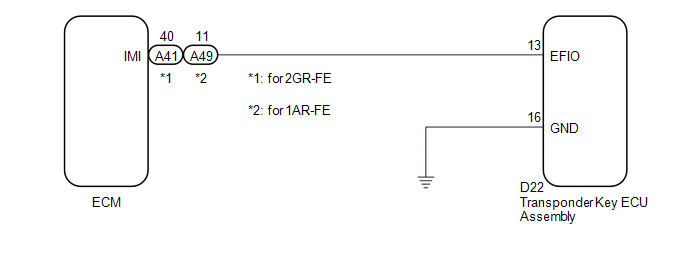
If the communication line (EFIO-IMI) to the transponder key ECU assembly is stuck high output (e.g. shorted to +B), the ECM stores this DTC.
|
DTC No. |
DTC Detection Condition |
Trouble Area |
|---|---|---|
|
B279A |
Communication line (EFIO-IMI) between the ECM and transponder key ECU assembly is stuck high output. |
|
WIRING DIAGRAM
CAUTION / NOTICE / HINT
NOTICE:
- If the transponder key ECU assembly is replaced, register the key and
ECU communication ID (See page
.gif) ).
).
- If the ECM is replaced, register the ECU communication ID (See page
).
PROCEDURE
|
1. |
CHECK DTC OUTPUT |
(a) Recheck for DTCs (See page ).
HINT:
If any DTCs other than DTC B279A are output, troubleshoot those DTCs first.
|
Result |
Proceed to |
|---|---|
|
DTC B279A is output |
A |
|
DTC B279A and other DTCs are output |
B |
| B | .gif) |
GO TO DTC CHART |
|
.gif)
|
2. |
CHECK HARNESS AND CONNECTOR (TRANSPONDER KEY ECU - ECM) |
(a) Disconnect the transponder key ECU assembly connector.
|
(b) Disconnect the ECM connector. |
|
(c) Measure the resistance and voltage according to the value(s) in the table below.
Standard Resistance:
for 2GR-FE|
Tester Connection |
Condition |
Specified Condition |
|---|---|---|
|
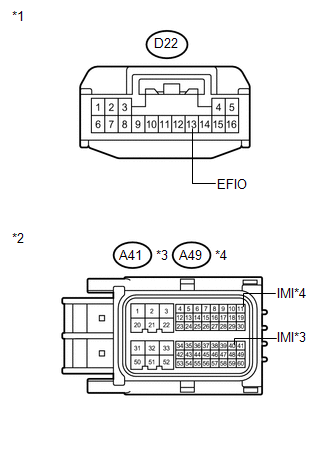
D22-13 (EFIO) - A41-40 (IMI) |
Always |
Below 1 Ω |
|
D22-13 (EFIO) - Body ground |
Always |
10 kΩ or higher |
|
A41-40 (IMI) - Body ground |
Always |
10 kΩ or higher |
|
Tester Connection |
Condition |
Specified Condition |
|---|---|---|
|
D22-13 (EFIO) - A49-11 (IMI) |
Always |
Below 1 Ω |
|
D22-13 (EFIO) - Body ground |
Always |
10 kΩ or higher |
|
A49-11 (IMI) - Body ground |
Always |
10 kΩ or higher |
Standard Voltage:
|
Tester Connection |
Condition |
Specified Condition |
|---|---|---|
|
D22-13 (EFIO) - Body ground |
Always |
Below 1 V |
|
*1 |
Front view of wire harness connector (to Transponder Key ECU Assembly) |
|
*2 |
Front view of wire harness connector (to ECM) |
|
*3 |
for 2GR-FE |
|
*4 |
for 1AR-FE |
| NG | |
REPAIR OR REPLACE HARNESS OR CONNECTOR |
|
|
3. |
CHECK TRANSPONDER KEY ECU ASSEMBLY (OUTPUT) |
(a) Reconnect the transponder key ECU assembly connector.
(b) Reconnect the ECM connector.
|
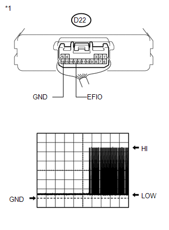
(c) Using an oscilloscope, check the waveform. Waveform 1 (Reference):
Result:
|
|
| B | |
REPLACE ECM |
| C | |
REPLACE ECM |
|
|
4. |
REPLACE TRANSPONDER KEY ECU ASSEMBLY |
(a) Replace the transponder key ECU assembly (See page
).
|
|
5. |
REGISTER KEY |
(a) Register the key (See page ).
|
|
6. |
REGISTER ECU COMMUNICATION ID |
(a) Register the ECU communication ID (See page
).
|
|
7. |
CHECK DTC OUTPUT |
(a) Clear the DTCs (See page ).
(b) Recheck for DTCs (See page ).
OK:
DTC B279A is not output.
|
Result |
Proceed to |
|---|---|
|
OK |
A |
|
NG (for 2GR-FE) |
B |
|
NG (for 1AR-FE) |
C |
| A | |
END (TRANSPONDER KEY ECU WAS DEFECTIVE) |
| B | |
REPLACE ECM |
| C | |
REPLACE ECM |
 Engine Immobiliser System Malfunction (B2799)
DESCRIPTION
This DTC is stored when one of the following occurs: 1) the ECM detects errors
in its own communications with the transponder key ECU assembly; 2) the ECM detects
errors in the commun ...
 Push Switch / Key Unlock Warning Switch Malfunction (B2780)
DESCRIPTION
This DTC is stored if the transponder key ECU assembly does not detect that the
unlock warning switch assembly is ON even when the ignition switch is ON. Under
normal conditions, the ...
Other materials about Toyota Venza:
Diagnosis System
DIAGNOSIS SYSTEM
1. DESCRIPTION
(a) The power back door ECU (power back door motor unit) controls the power back
door system functions. Power back door system data and Diagnostic Trouble Code (DTC)
can be read through the Data Link Connector 3 (DLC3).
W ...
Operation Check
OPERATION CHECK
1. INSPECT ILLUMINATED ENTRY SYSTEM OPERATION
NOTICE:
Perform this inspection with the customize parameters at the initial setting.
HINT:
The interior light control illuminates the lights below.
Transponder Key Amplifier*1
Roof ...
Diagnostic Trouble Code Chart
DIAGNOSTIC TROUBLE CODE CHART
HINT:
If a trouble code is displayed during the DTC check, inspect the circuit listed
for that code. For details of each code, refer to the relevant page listed under
respective "DTC Code" in the DTC chart.
Tire P ...

0.1537