Toyota Venza: Push Switch / Key Unlock Warning Switch Malfunction (B2780)
DESCRIPTION
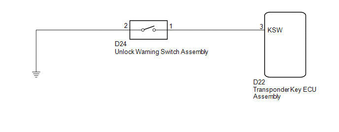
This DTC is stored if the transponder key ECU assembly does not detect that the unlock warning switch assembly is ON even when the ignition switch is ON. Under normal conditions, the unlock warning switch assembly is ON when the ignition switch is ON.
|
DTC No. |
DTC Detection Condition |
Trouble Area |
|---|---|---|
|
B2780 |
"Unlock warning switch ON" is not detected when the ignition switch is ON. |
|
WIRING DIAGRAM
CAUTION / NOTICE / HINT
NOTICE:
If the transponder key ECU assembly is replaced, register the key and ECU communication
ID (See page .gif) ).
).
PROCEDURE
|
1. |
READ VALUE USING TECHSTREAM |
(a) Connect the Techstream to the DLC3.
(b) Turn the ignition switch to ON.
(c) Turn the Techstream on.
(d) Enter the following menus: Body Electrical / Immobiliser / Data List.
(e) Read the Data List according to the display on the Techstream.
Immobiliser (Transponder Key ECU Assembly)|
Tester Display |
Measurement Item/Range |
Normal Condition |
Diagnostic Note |
|---|---|---|---|
|
Key SW |
Unlock warning switch signal/ON or OFF |
ON: Key in ignition key cylinder OFF: No key in ignition key cylinder |
- |
OK:
On the Techstream screen, the item changes between ON and OFF according to the chart above.
| OK | .gif) |
REPLACE TRANSPONDER KEY ECU ASSEMBLY |
|
.gif)
|
2. |
INSPECT UNLOCK WARNING SWITCH ASSEMBLY |
|
(a) Remove the unlock warning switch assembly (See page
|
|
.png)
(b) Measure the resistance according to the value(s) in the table below.
Standard Resistance:
|
Tester Connection |
Switch Condition |
Specified Condition |
|---|---|---|
|
1 - 2 |
Switch pushed (Key set) |
Below 1 Ω |
|
1 - 2 |
Switch free (Key removed) |
10 kΩ or higher |
|
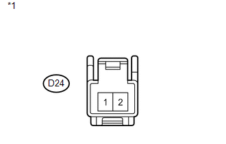
*1 |
Component without harness connected (Unlock Warning Switch Assembly) |
| NG | |
REPLACE UNLOCK WARNING SWITCH ASSEMBLY |
|
|
3. |
CHECK HARNESS AND CONNECTOR (UNLOCK WARNING SWITCH - BODY GROUND) |
|
(a) Measure the resistance according to the value(s) in the table below. Standard Resistance:
|
|
| NG | |
REPAIR OR REPLACE HARNESS OR CONNECTOR |
|
|
4. |
CHECK HARNESS AND CONNECTOR (TRANSPONDER KEY ECU - UNLOCK WARNING SWITCH) |
|
(a) Disconnect the transponder key ECU assembly connector. |
|
(b) Measure the resistance according to the value(s) in the table below.
Standard Resistance:
|
Tester Connection |
Condition |
Specified Condition |
|---|---|---|
|
D22-3 (KSW) - D24-1 |
Always |
Below 1 Ω |
|
D22-3 (KSW) - Body ground |
Always |
10 kΩ or higher |
|
D24-1 - Body ground |
Always |
10 kΩ or higher |
|
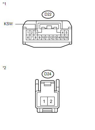
*1 |
Front view of wire harness connector (to Transponder Key ECU Assembly) |
|
*2 |
Front view of wire harness connector (to Unlock Warning Switch Assembly) |
| OK | |
REPLACE TRANSPONDER KEY ECU ASSEMBLY |
| NG | |
REPAIR OR REPLACE HARNESS OR CONNECTOR |
 Theft Deterrent System Communication Line High Fixation (B279A)
DESCRIPTION
If the communication line (EFIO-IMI) to the transponder key ECU assembly is stuck
high output (e.g. shorted to +B), the ECM stores this DTC.
DTC No.
DTC Detection ...
 Antenna Coil Open / Short (B2784)
DESCRIPTION
The transponder key coil is built into the transponder key amplifier and receives
a key code signal from the transponder chip in the key. This signal is amplified
by the amplifier, th ...
Other materials about Toyota Venza:
System Diagram
SYSTEM DIAGRAM
Communication Table
Sender
Receiver
Signal
Line
Main body ECU (Driver side junction block assembly)
Power back door ECU (Power back door motor unit)
...
Tire Pressure Warning Ecu
Components
COMPONENTS
ILLUSTRATION
ILLUSTRATION
Removal
REMOVAL
CAUTION / NOTICE / HINT
NOTICE:
Before removing the tire pressure warning ECU, read the registered transmitter
IDs of all wheels and write them down to use for re-registration of ...
Customize Parameters
CUSTOMIZE PARAMETERS
HINT:
The following items can be customized.
NOTICE:
After confirming whether the items requested by the customer are applicable
or not for customization, perform customizing operations.
Be sure to record the current se ...

0.1244