Toyota Venza: Knock Sensor
Components
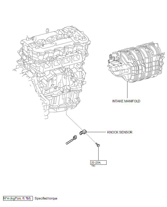
COMPONENTS
ILLUSTRATION
Removal
REMOVAL
PROCEDURE
1. REMOVE INTAKE MANIFOLD
(a) Remove the intake manifold (See page .gif) ).
).
2. REMOVE KNOCK SENSOR
|
(a) Disconnect the sensor connector. |
|
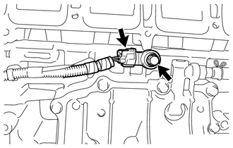
(b) Remove the bolt and sensor.
Inspection
INSPECTION
PROCEDURE
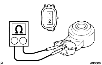
1. INSPECT KNOCK SENSOR
|
(a) Measure the resistance according to the value(s) in the table below. Standard Resistance:
If the result is not as specified, replace the knock sensor. |
|
Installation
INSTALLATION
PROCEDURE
1. INSTALL KNOCK SENSOR
|
(a) Install the sensor with the bolt so that the sensor is angled as shown in the illustration. Torque: 20 N·m {204 kgf·cm, 15 ft·lbf} NOTICE: The acceptable installation angle of the sensor is between 7° upward and 10° downward from the horizontal position. HINT: Perform "Inspection After Repair" after replacing the knock control sensor
(See page |
|

(b) Connect the sensor connector.
2. INSTALL INTAKE MANIFOLD
(a) Install the intake manifold (See page .gif)
).
 On-vehicle Inspection
ON-VEHICLE INSPECTION
PROCEDURE
1. PERFORM SPARK TEST
(a) Check for DTCs (See page ).
NOTICE:
If any DTC is output, perform troubleshooting procedures for that DTC.
(b) Remove the ignition coil ...
 Mass Air Flow Meter
Components
COMPONENTS
ILLUSTRATION
On-vehicle Inspection
ON-VEHICLE INSPECTION
CAUTION / NOTICE / HINT
NOTICE:
Perform the mass air flow meter inspection according to the procedur ...
Other materials about Toyota Venza:
Engine Circuit Malfunction (C1280/82)
DESCRIPTION
If a malfunction in the ECM circuit occurs, the AWD control ECU will output this
DTC.
DTC No.
DTC Detection Condition
Trouble Area
C1280/82
When the following continues for ...
System Description
SYSTEM DESCRIPTION
1. GENERAL
This system has the following functions: manual slide open and close; auto slide
open; manual tilt up and down; auto tilt up; jam protection; key off operation.
2. FUNCTION OF MAIN COMPONENT
Component
O ...
System Diagram
SYSTEM DIAGRAM
Communication Method
Transmitting ECU
Receiver
Signal
Communication Method
Main body ECU (Driver Side Junction Block Assembly)
Power back door ECU (Power back door motor ...

0.1196