Toyota Venza: Terminals Of Ecu
TERMINALS OF ECU
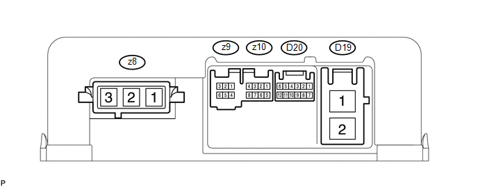
1. CHECK POWER STEERING ECU
HINT:
As connector z8 uses a lock lever, each terminal cannot be checked while the connector is still connected to the power steering ECU.
|
Terminal No. (Symbol) |
Wiring Color |
Terminal Description |
|---|---|---|
|
z8-1 (V) |
W |
V phase motor output |
|
z8-2 (U) |
B |
U phase motor output |
|
z8-3 (W) |
R |
W phase motor output |
(a) Measure the voltage and resistance according to the value(s) in the table below.
NOTICE:
When the P/S warning light is illuminated during a malfunction, the fail-safe function may cause the voltage of the power steering ECU terminals to become 0 V.
|
Terminal No. (Symbol) |
Wiring Color |
Terminal Description |
Condition |
Specified Condition |
|---|---|---|---|---|
|
D19-1 (PIG) - D19-2 (PGND) |
R - B |
Power source |
Always |
11 to 14 V |
|
D19-2 (PGND) - Body ground |
B - Body ground |
Power ground |
Always |
Below 1 Ω |
|
D20-1 (CANH) - D20-7 (CANL) |
BR - W |
CAN communication line |
Ignition switch off |
54 to 69 Ω |
|
D20-6 (IG) - D19-2 (PGND) |
GR - B |
IG power source |
Ignition switch ON |
11 to 14 V |
|
z9-1 (RZV) - D19-2 (PGND) |
R - B |
Rotation angle sensor excitation output signal |
Engine running, steering wheel being turned |
-2.42 to 2.42 V |
|
z9-3 (RZG) - D19-2 (PGND) |
B - B |
Rotation angle sensor excitation circuit GND |
Always |
Below 1 Ω |
|
z9-5 (RZCS) - D19-2 (PGND) |
L - B |
Rotation angle sensor COS aspect output signal |
Engine running, steering wheel being turned |
-0.73 to 0.73 V |
|
z9-6 (RZSN) - D19-2 (PGND) |
Y - B |
Rotation angle sensor SIN aspect output signal |
Engine running, steering wheel being turned |
-0.73 to 0.73 V |
|
z10-5 (TRQ1) - z10-8 (TRQG) |
W - B |
Torque sensor signal |
Engine running, steering wheel not turned (without load) |
2.3 to 2.7 V |
|
Engine running, steering wheel turned to right with vehicle stopped |
2.5 to 3.8 V |
|||
|
Engine running, steering wheel turned to left with vehicle stopped |
1.2 to 2.5 V |
|||
|
z10-6 (TRQV) - z10-8 (TRQG) |
R - B |
Torque sensor voltage source |
Ignition switch ON |
4.5 to 5.5 V |
|
z10-7 (TRQ2) - z10-8 (TRQG) |
Y - B |
Torque sensor signal |
Engine running, steering wheel not turned (without load) |
2.3 to 2.7 V |
|
Engine running, steering wheel turned to right with vehicle stopped |
1.2 to 2.5 V |
|||
|
Engine running, steering wheel turned to left with vehicle stopped |
2.5 to 3.8 V |
|||
|
z10-8 (TRQG) - Body ground |
B - Body ground |
Torque sensor ground |
Always |
Below 1 Ω |
If the result is not as specified, the ECU may have a malfunction.
 Problem Symptoms Table
PROBLEM SYMPTOMS TABLE
HINT:
Use the table below to help determine the cause of problem symptoms.
If multiple suspected areas are listed, the potential causes of the symptoms
are lis ...
 Diagnosis System
DIAGNOSIS SYSTEM
1. CHECK DLC3
(a) Check the DLC3 (See page ).
2. FUNCTION OF P/S WARNING LIGHT
(a) When a malfunction is detected in the power steering system, the P/S warning
light on the acc ...
Other materials about Toyota Venza:
Crankshaft Position Sensor
Components
COMPONENTS
ILLUSTRATION
Removal
REMOVAL
PROCEDURE
1. REMOVE FRONT FENDER APRON SEAL RH
2. REMOVE CRANKSHAFT POSITION SENSOR
(a) Disconnect the sensor connector.
(b) Remove the bolt and sensor.
Inspection
INSPECTION
PROCEDURE ...
Installation
INSTALLATION
CAUTION / NOTICE / HINT
HINT:
Use the same procedure for the RH side and LH side.
The procedure listed below is for the LH side.
PROCEDURE
1. INSTALL DOOR SIDE AIRBAG SENSOR
(a) Check that the ignition switch is off.
(b) C ...
Manual Shifting Test
MANUAL SHIFTING TEST
1. PERFORM MANUAL SHIFTING TEST
HINT:
Using this test, it can be determined whether a problem is in an electrical
circuit or if it is a mechanical problem in the transaxle.
If any abnormalities are found in the following ...

0.1291