Toyota Venza: Removal
REMOVAL
CAUTION / NOTICE / HINT
NOTICE:
When disconnecting the steering intermediate shaft assembly and pinion shaft of steering gear assembly, be sure to place matchmarks before servicing.
PROCEDURE
1. PLACE FRONT WHEELS FACING STRAIGHT AHEAD
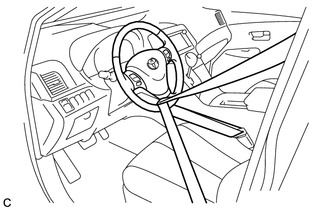
2. SECURE STEERING WHEEL
|
(a) Secure the steering wheel with the seat belt in order to prevent it from rotating. HINT: This operation is necessary to prevent damage to the spiral cable. |
|
3. REMOVE FRONT WHEELS
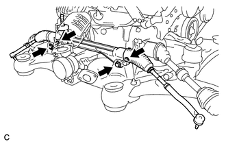
4. SEPARATE STEERING INTERMEDIATE SHAFT ASSEMBLY
|
(a) Remove the bolt and slide the steering intermediate shaft assembly. NOTICE: Do not separate the steering intermediate shaft assembly from the steering link assembly. |
|
.png)
|
(b) Put matchmarks on the steering intermediate shaft assembly and steering link assembly. Text in Illustration
|
|
.png)
(c) Separate the steering intermediate shaft assembly from the steering link assembly.
5. SEPARATE TIE ROD ASSEMBLY LH
|
(a) Remove the cotter pin and nut. |
|
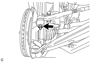
|
(b) Install SST to the tie rod end. SST: 09960-20010 09961-02060 NOTICE: Make sure that the upper ends of the tie rod end and SST are aligned. |
|
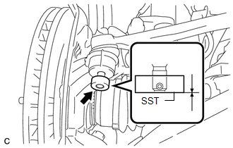
(c) Using SST, separate the tie rod end from the steering knuckle.
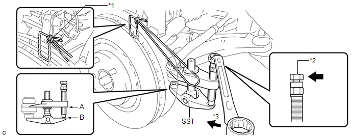 Text in Illustration
|
*1 |
Tie the string without allowing for any slack. |
|
*2 |
Place the wrench here. |
|
*3 |
Turn |
SST: 09960-20010
09961-02010
CAUTION:
Apply grease to the threads and end of the SST bolt.
NOTICE:
- When securing SST to the steering knuckle, be sure to tighten SST using a string to prevent it from falling.
- Install SST so that A and B are parallel.
- Be sure to place a wrench on the part indicated in the illustration.
- Do not damage the front disc brake dust cover.
- Do not damage the ball joint dust cover.
- Do not damage the steering knuckle.
6. SEPARATE TIE ROD ASSEMBLY RH
HINT:
Perform the same procedure as for the LH side.
7. REMOVE ENGINE ASSEMBLY WITH TRANSAXLE
- for 2GR-FE: (See page
.gif) )
) - for 1AR-FE: (See page )
8. SEPARATE FRONT NO. 1 STABILIZER BRACKET LH
9. SEPARATE FRONT NO. 1 STABILIZER BRACKET RH
HINT:
Perform the same procedure as for the LH side.
10. REMOVE FRONT STABILIZER BAR WITH BRACKET
11. REMOVE STEERING LINK ASSEMBLY
|
(a) Remove the 2 bolts, 2 nuts and steering link assembly. NOTICE: Because the nut has its own stopper, do not turn the nut. Loosen the bolt with the nut secured. |
|
12. REMOVE TIE ROD ASSEMBLY LH
|
(a) Put matchmarks on the tie rod assembly LH and steering rack end sub-assembly. Text in Illustration
|
|
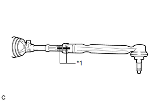
(b) Loosen the lock nut, and remove the tie rod assembly LH and lock nut.
13. REMOVE TIE ROD ASSEMBLY RH
HINT:
Perform the same procedure as for the LH side.
 Components
COMPONENTS
ILLUSTRATION
ILLUSTRATION
ILLUSTRATION
ILLUSTRATION
ILLUSTRATION
...
 Disassembly
DISASSEMBLY
PROCEDURE
1. REMOVE STEERING RACK BOOT CLIP (for LH Side)
(a) Using pliers, remove the steering rack boot clip.
2. REMOVE STEERING RACK BOOT CLIP (for RH Side)
HINT:
Perform the same ...
Other materials about Toyota Venza:
Terminals Of Ecu
TERMINALS OF ECU
1. CHECK ENGINE SWITCH
(a) Disconnect the D13 engine switch connector.
(b) Measure the resistance according to the value(s) in the table below.
HINT:
Measure the values on the wire harness side with connector disconnected.
T ...
Satellite Radio Broadcast cannot be Selected or After Selecting Broadcast, Broadcast
cannot be Added into Memory
CAUTION / NOTICE / HINT
NOTICE:
Some satellite radio broadcasts require payment. A contract must be made between
a satellite radio company and the user. If the contract expires, it will not be
possible to listen to the broadcast.
PROCEDURE
1 ...
Headlight Solenoid Circuit
DESCRIPTION
for HID Headlight:
When the main body ECU receives a high beam turn on signal, the main
body ECU activates the bi-function by controlling the BI-XENON relay. The
bi-function increases the upper illumination area of the discharge ...

0.1338