Toyota Venza: Installation
INSTALLATION
PROCEDURE
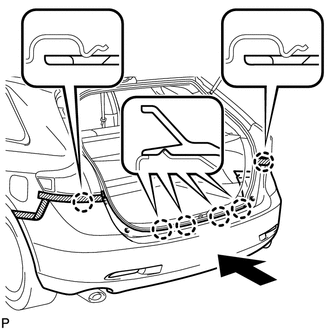
1. INSTALL REAR BUMPER ASSEMBLY
(a) w/ Intuitive Parking Assist System:
(1) Connect each connector.
|
(b) Engage the 6 claws and install the rear bumper assembly as shown in the illustration. |
|
|
(c) Engage the 5 claws. HINT: Use the same procedure for the RH side and LH side. |
|
|
(d) Install the screw. HINT: Use the same procedure for the RH side and LH side. |
|
.png)
|
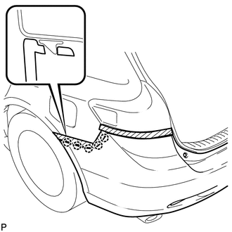
(e) Engage the 2 clips and install the 2 screws. |
|
.png)
|
(f) Install the 2 bolts and 2 screws. Torque: Bolt : 5.5 N·m {56 kgf·cm, 49 in·lbf} |
|
.png)
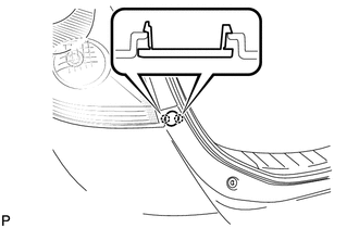
(g) Engage the 2 clips.
2. INSTALL REAR BUMPER PLATE LH
|
(a) Engage the 2 claws and install the rear bumper plate LH. |
|
3. INSTALL REAR BUMPER PLATE RH
HINT:
Use the same procedure for the RH side and LH side.
 Disassembly
DISASSEMBLY
PROCEDURE
1. REMOVE ULTRASONIC SENSOR CLIP (w/ Intuitive Parking Assist System)
2. REMOVE NO. 1 ULTRASONIC SENSOR (w/ Intuitive Parking Assist System)
3. REMOVE NO. 1 ULTRASONIC ...
 Reassembly
REASSEMBLY
PROCEDURE
1. INSTALL NO. 1 REAR BUMPER REINFORCEMENT
(a) Install the No. 1 rear bumper reinforcement with the 6 nuts.
Torque:
68 N·m {693 kgf·cm, 50 ft·lbf}
...
Other materials about Toyota Venza:
Control Module Communication Bus OFF (U0073/86,U0100/85,U0129/83)
DESCRIPTION
The AWD control ECU inputs the signals sent from the ECM and skid control
ECU via the CAN communication system.
When DTCs indicating a CAN communication system malfunction are output,
repair the CAN communication system before r ...
Fuel Sender Open Detected (B1500)
DESCRIPTION
This DTC is output when the combination meter assembly detects a fuel sender
gauge malfunction via the direct line.
DTC No.
DTC Detection Condition
Trouble Area
B1500
When either of t ...
Problem Symptoms Table
PROBLEM SYMPTOMS TABLE
HINT:
Use the table below to help determine the cause of problem symptoms. If multiple
suspected areas are listed, the potential causes of the symptoms are listed in order
of probability in the "Suspected Area" column of ...

0.163