Toyota Venza: TC and CG Terminal Circuit
DESCRIPTION
Connecting terminals TC and CG of the DLC3 causes the AWD control ECU to display 2-digit DTCs by flashing the AWD warning light.
HINT:
When each warning light remains blinking, a short to ground in the wiring of terminal TC of the DLC3 or an internal short to ground in each ECU is suspected.
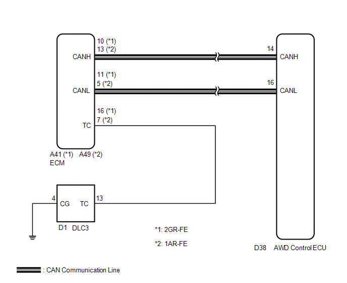
WIRING DIAGRAM
CAUTION / NOTICE / HINT
HINT:
Check the condition of each related circuit connector before troubleshooting
(See page .gif) ).
).
PROCEDURE
|
1. |
CHECK CAN COMMUNICATION SYSTEM |
(a) Check if the CAN communication DTC is output (See page
).
|
Result |
Proceed to |
|---|---|
|
DTC is not output |
A |
|
DTC is output |
B |
| B | .gif) |
REPAIR CAN COMMUNICATION SYSTEM |
|
.gif)
|
2. |
CHECK WIRE HARNESS (TC OF DLC3 - TC OF ECM AND BODY GROUND) |
|
(a) Turn the ignition switch off. |
|
(b) Disconnect the ECM connector.
(c) Measure the resistance of the wire harness side connectors.
Standard Resistance:
|
Tester Connection (DLC3 - ECM) |
Condition |
Specified Condition |
|---|---|---|
|
D1-13 (TC) - A41-16 (TC) |
Always |
Below 1 Ω |
|
D1-13 (TC) - A49-7 (TC) |
Always |
Below 1 Ω |
|
D1-13 (TC) - Body Ground |
Always |
10 kΩ or higher |
|
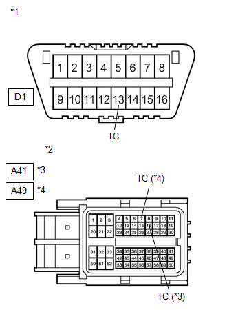
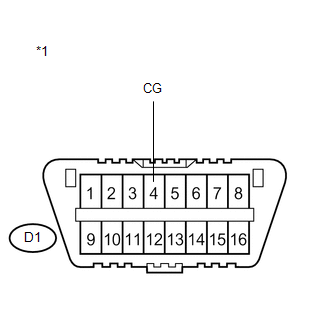
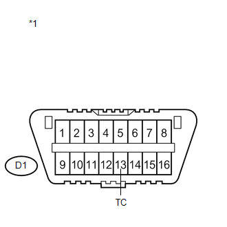
*1 |
DLC3 |
|
*2 |
Front view of wire harness connector (to ECM) |
|
*3 |
2GR-FE |
|
*4 |
1AR-FE |
| NG | |
REPAIR OR REPLACE HARNESS OR CONNECTOR |
|
|
3. |
CHECK WIRE HARNESS (CG OF DLC3 - BODY GROUND) |
|
(a) Measure the resistance of the DLC3. Standard Resistance:
|
|
| NG | |
REPAIR OR REPLACE HARNESS OR CONNECTOR |
|
|
4. |
CHECK WIRE HARNESS (TC OF DLC3 - BODY GROUND) |
|
(a) Measure the resistance of the DLC3. Standard Resistance:
|
|
| OK | |
REPLACE AWD CONTROL ECU |
| NG | |
REPAIR OR REPLACE HARNESS OR CONNECTOR |
 AWD Warning Light Remains ON
DESCRIPTION
The AWD control ECU is connected to the combination meter via the CAN communication
system.
If the AWD control ECU stores any DTCs which are related to the active torque
control 4WD ...

Other materials about Toyota Venza:
Using the automatic mode
Press
.
The air conditioning system will begin to operate. In outside air or recirculated
air mode, air outlets, fan speed and air conditioning on/ off are automatically
adjusted according to the temperature setting.
“AUTO” will be displayed on th ...
Passenger Side Buckle Switch Circuit Malfunction (B1771)
DESCRIPTION
The passenger side buckle switch circuit consists of the occupant classification
ECU and front seat inner belt assembly RH.
DTC B1771 is recorded when a malfunction is detected in the passenger side buckle
switch circuit.
Troubleshoot DTC B1 ...
Installation
INSTALLATION
PROCEDURE
1. INSTALL AIR CONDITIONING UNIT ASSEMBLY
(a) Install the air conditioning unit assembly with the 3 nuts.
Torque:
9.8 N·m {100 kgf·cm, 87 in·lbf}
NOTICE:
Tighten the nuts in the order shown in the illustration to install the ...

0.1284