Toyota Venza: System Diagram
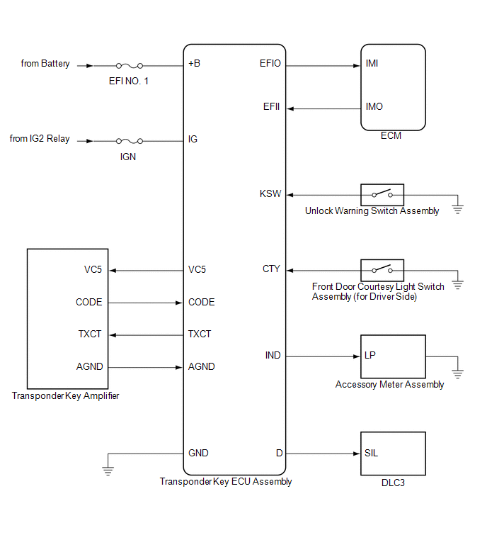
SYSTEM DIAGRAM
 System Description
SYSTEM DESCRIPTION
1. ENGINE IMMOBILISER SYSTEM DESCRIPTION
The engine immobiliser system is designed to prevent the vehicle from being stolen.
This system uses the transponder key ECU assembly th ...
 How To Proceed With Troubleshooting
CAUTION / NOTICE / HINT
HINT:
Use the following procedure to troubleshoot the engine immobiliser system.
*: Use the Techstream.
PROCEDURE
1.
VEHICLE BROUGHT TO WORKSHOP
...
Other materials about Toyota Venza:
Slide Sensor Malfunction (B2650)
DESCRIPTION
When the position control ECU and switch assembly does not receive a sensor signal
despite forward or backward movement of seat by power seat motor operation, this
DTC is output.
DTC Code
DTC Detection Condition
...
Reassembly
REASSEMBLY
PROCEDURE
1. CONNECT WASHER HOSE ASSEMBLY
(a) Engage the 5 clips and connect the washer hose assembly.
2. INSTALL FRONT WASHER NOZZLE SUB-ASSEMBLY
3. INSPECT FRONT WASHER NOZZLE SUB-A ...
Front Passenger Side Seat Belt Warning Light Malfunction
DESCRIPTION
The occupant classification ECU detects the state of the front seat inner belt
assembly RH and load sensor when the front passenger side seat is occupied with
the ignition switch ON. If the front passenger side seat belt is not fastened, the
...

0.1433