Toyota Venza: Removal
REMOVAL
PROCEDURE
1. REMOVE UPPER CONSOLE PANEL SUB-ASSEMBLY (w/o Seat Heater System)
.gif)
2. REMOVE UPPER CONSOLE PANEL SUB-ASSEMBLY (w/ Seat Heater System)
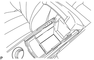
3. REMOVE NO. 2 CONSOLE BOX CARPET
|
(a) Remove the No. 2 console box carpet. |
|
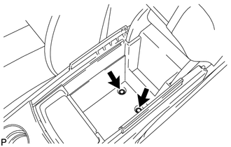
4. REMOVE CONSOLE BOX ASSEMBLY
|
(a) Remove the 2 bolts. |
|
|
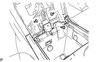
(b) Remove the screw and 2 clips. |
|
|
(c) Disengage the 2 claws. |
|
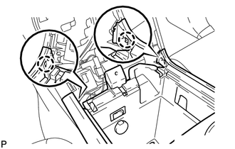
(d) Disconnect the connectors and remove the console box assembly.
 Disassembly
DISASSEMBLY
PROCEDURE
1. REMOVE NO. 1 CONSOLE BOX CARPET
(a) Remove the No. 1 console box carpet.
2. REMOVE INSTRUMENT PANEL CUP HOLDER DA ...
 Installation
INSTALLATION
PROCEDURE
1. INSTALL CONSOLE BOX ASSEMBLY
(a) Connect the connectors.
(b) Engage the 2 claws.
(c) Install the scr ...
Other materials about Toyota Venza:
Installation
INSTALLATION
PROCEDURE
1. INSTALL WINDSHIELD WIPER SWITCH ASSEMBLY
(a) Engage the claw to install the windshield wiper switch assembly as
shown in the illustration.
(b) Connect the 2 connectors. ...
Vsc Off Switch
Components
COMPONENTS
ILLUSTRATION
Removal
REMOVAL
PROCEDURE
1. DISCONNECT CABLE FROM NEGATIVE BATTERY TERMINAL
NOTICE:
When disconnecting the cable, some systems need to be initialized after the cable
is reconnected (See page ).
2. REMOVE FR ...
Diagnosis System
DIAGNOSIS SYSTEM
1. DESCRIPTION
(a) Lighting system data and the Diagnostic Trouble Codes (DTCs) can be read
from the Data Link Connector 3 (DLC3) of the vehicle. When the system seems to be
malfunctioning, use the Techstream to check for malfunctions an ...

0.1617