Toyota Venza: System Diagram
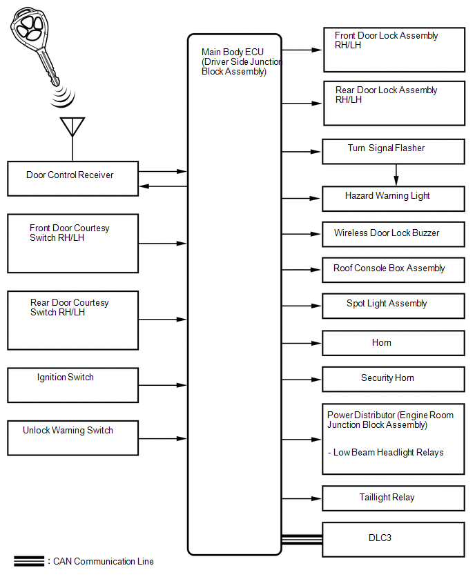
SYSTEM DIAGRAM
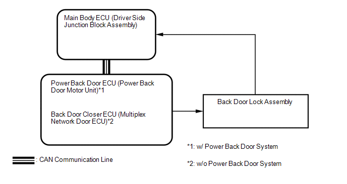 Communication Table
|
Transmitting ECU (Transmitter) |
Receiving ECU (Receiver) |
Signal |
Line |
|---|---|---|---|
|
Main body ECU (Driver side junction block assembly) |
Power Back Door ECU (Power Back door motor unit)*1 Back Door Closer ECU (Multiplex Network Door ECU)*2 |
Power back door control signal |
CAN |
- *1: w/ Power Back Door System
- *2: w/o Power Back Door System
 System Description
SYSTEM DESCRIPTION
1. WIRELESS DOOR LOCK CONTROL SYSTEM
The wireless door lock control system functions to lock and unlock all the doors
from a distance. The system is controlled by a door control ...
 How To Proceed With Troubleshooting
CAUTION / NOTICE / HINT
HINT:
The wireless door lock control system troubleshooting procedures are
based on the premise that the power door lock control system is operating
normally. ...
Other materials about Toyota Venza:
Erasing the entire HomeLink® memory (all three programs)
Press and hold the 2 outside buttons for 10 seconds (or 20 seconds depending
on the model) until the indicator light flashes.
If you sell your vehicle, be sure to erase the programs stored in the HomeLink®
memory.
- Before programming
• Insta ...
Lost Communication with AFS ECU (U0182)
DESCRIPTION
DTC No.
DTC Detection Condition
Trouble Area
U0182
No communication from the AFS ECU continues.
AFS ECU branch wire or connector
Power source circuit of AFS E ...
Installation
INSTALLATION
PROCEDURE
1. INSTALL FUEL PRESSURE PULSATION DAMPER ASSEMBLY
(a) Apply a light coat of gasoline or spindle oil to a new O-ring.
Text in Illustration
*1
O-ring
...

0.1555