Toyota Venza: Removal
REMOVAL
CAUTION / NOTICE / HINT
HINT:
- The front side fix window assembly can be reused. When installing the window, if any of the clips on the front side fix window assembly are broken, butyl tape can be used to support the glass until the applied adhesive hardens.
- When using butyl tape to temporarily secure the window, make sure that the butyl tape is not applied exactly at the original clip location. If the butyl tape is applied exactly at the clip location, it will cause the window to protrude.
- Use the same procedure for the RH side and LH side.
- The procedure listed below is for the LH side.
PROCEDURE
1. DISCONNECT FRONT DOOR OPENING TRIM WEATHERSTRIP
(a) Remove the front part of the front door opening trim weatherstrip to the extent that allows removal of the front pillar garnish.
2. REMOVE FRONT PILLAR GARNISH
.gif)
3. REMOVE FRONT PILLAR GARNISH CORNER PIECE (for 6 Speakers)
4. REMOVE FRONT PILLAR GARNISH CORNER PIECE (for 13 Speakers)
5. REMOVE FRONT SIDE FIX WINDOW ASSEMBLY
|
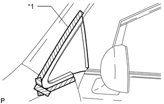
(a) Apply protective tape to the installation position of the front side fix window assembly on the vehicle body. Text in Illustration
|
|
|
(b) Place matchmarks on the front side fix window assembly and vehicle body on the locations indicated in the illustration. Text in Illustration
HINT: Matchmarks are not necessary if the front side fix window assembly is not going to be reused. |
|
.png)
|
(c) Pass a piano wire between the interior vehicle body and glass from the interior as shown in the illustration. HINT: Do not allow the piano wire to interfere with the clips. |
|
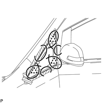
(d) Tie both wire ends to wooden blocks or similar objects that can serve as handles.
NOTICE:
When separating the front side fix window assembly from the vehicle, be careful not to damage the paint or interior and exterior ornaments.
(e) Cut off the adhesive by pulling the piano wire around the front side fix window assembly.
NOTICE:
Leave as much adhesive on the vehicle body as possible when cutting through the adhesive.
|
(f) Disengage the 3 clips. |
|
.png)
(g) Using suction cups, remove the glass.
NOTICE:
Be careful not to drop the glass.
6. CLEAN VEHICLE BODY
|
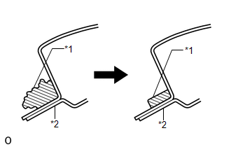
(a) Clean and shape the contact surfaces of the vehicle body. Text in Illustration
(1) Using a knife, cut away excess adhesive on the contact surfaces of the vehicle body as shown in the illustration. NOTICE: Be careful not to damage the vehicle body. HINT: Leave as much adhesive on the vehicle body as possible. |
|
(b) Clean the contact surfaces of the vehicle body with a piece of cloth saturated with cleaner.
HINT:
Even if all the adhesive has been removed, clean the vehicle body.
 Installation
INSTALLATION
PROCEDURE
1. CLEAN FRONT SIDE FIX WINDOW ASSEMBLY
(a) Clean the outer edges of the front side fix window assembly with
a non-residue solvent.
NOTICE:
...

Other materials about Toyota Venza:
Removal
REMOVAL
CAUTION / NOTICE / HINT
HINT:
Use the same procedure for the RH side and LH side.
The procedure listed below is for the LH side.
PROCEDURE
1. REMOVE REAR WHEEL
2. SEPARATE REAR FLEXIBLE HOSE
3. SEPARATE REAR DISC BRAKE CALIP ...
Relay
On-vehicle Inspection
ON-VEHICLE INSPECTION
PROCEDURE
1. INSPECT STARTER RELAY
(a) Measure the resistance according to the value(s) in the table below.
Standard Resistance:
Tester Connection
Condition
...
Inspection
INSPECTION
PROCEDURE
1. INSPECT OUTER MIRROR SWITCH ASSEMBLY (w/o Memory)
(a) The L position of the left/right adjustment switch: Measure the resistance
according to the value(s) in the table below.
Standard Resistance (for Left Side):
Tes ...

0.1632