Toyota Venza: System Diagram
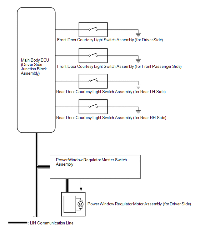
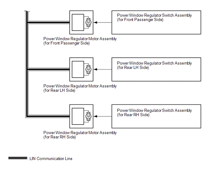
SYSTEM DIAGRAM
 Communication Table
|
Transmitting ECU |
Receiving ECU |
Signal |
Communication Method |
|---|---|---|---|
|
Power window regulator master switch assembly |
Power window regulator motor assembly (for driver side) |
Power window auto up and down signal |
LIN |
|
Power window remote up and down signal |
LIN |
|
|
Main body ECU (driver side junction block assembly) |
|
Power window operation permission signal |
LIN |
 Parts Location
PARTS LOCATION
ILLUSTRATION
ILLUSTRATION
...
 How To Proceed With Troubleshooting
CAUTION / NOTICE / HINT
HINT:
Use the following procedure to troubleshoot the power window control
system.
*: Use the Techstream.
PROCEDURE
1.
VEHICLE ...
Other materials about Toyota Venza:
Back Door cannot be Opened
DESCRIPTION
When the back door cannot be opened, one of the following may be malfunctioning:
1) power back door ECU (power back door motor unit)*1 or back door closer ECU (multiplex
network door ECU)*2, 2) back door lock assembly, 3) back door opener swit ...
Seat Belt Buckle Switch LH Circuit Malfunction (B1656/38)
DESCRIPTION
The seat belt buckle switch LH circuit consists of the center airbag sensor assembly
and front seat inner belt assembly LH.
DTC B1656/38 is stored when a malfunction is detected in the seat belt buckle
switch LH circuit.
DTC No.
...
Removal
REMOVAL
PROCEDURE
1. REMOVE BACK DOOR PANEL TRIM ASSEMBLY
2. REMOVE REAR WIPER ARM HEAD CAP
3. REMOVE REAR WIPER ARM AND BLADE ASSEMBLY
4. REMOVE REAR WIPER MOTOR GROMMET
5. REMOVE REAR WIPER MOTOR AND BRACKET ASSEMBLY
6. REMOVE REAR LIGH ...

0.1394