Toyota Venza: Air Conditioning Panel
Components
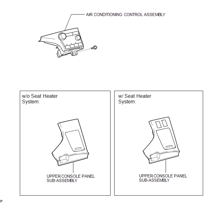
COMPONENTS
ILLUSTRATION
Installation
INSTALLATION
PROCEDURE
1. INSTALL AIR CONDITIONING CONTROL ASSEMBLY
(a) Connect the connector.
|
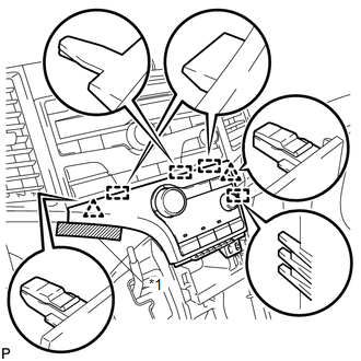
(b) Engage the 2 clips and 4 guides. |
|
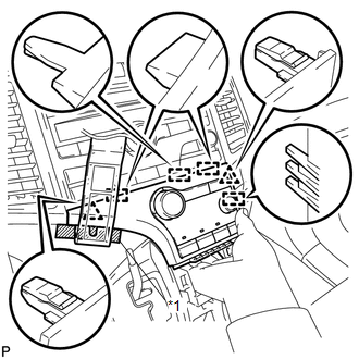
(c) Remove the protective tape.
Text in Illustration|
*1 |
Protective Tape |
|
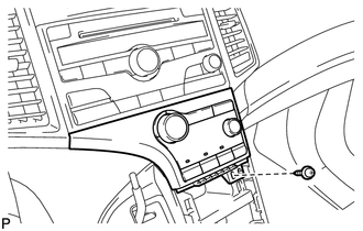
(d) Install the air conditioning control assembly with the screw. |
|
2. INSTALL UPPER CONSOLE PANEL SUB-ASSEMBLY (w/o Seat Heater System)
.gif)
3. INSTALL UPPER CONSOLE PANEL SUB-ASSEMBLY (w/ Seat Heater System)
4. CONNECT CABLE TO NEGATIVE BATTERY TERMINAL
NOTICE:
When disconnecting the cable, some systems need to be initialized after the cable
is reconnected (See page ).
Removal
REMOVAL
PROCEDURE
1. DISCONNECT CABLE FROM NEGATIVE BATTERY TERMINAL
NOTICE:
When disconnecting the cable, some systems need to be initialized after the cable
is reconnected (See page .gif) ).
).
2. REMOVE UPPER CONSOLE PANEL SUB-ASSEMBLY (w/o Seat Heater System)
3. REMOVE UPPER CONSOLE PANEL SUB-ASSEMBLY (w/ Seat Heater System)
4. REMOVE AIR CONDITIONING CONTROL ASSEMBLY
|
(a) Remove the screw. |
|
.png)
|
(b) Apply protective tape to the area shown in the illustration. Text in Illustration
|
|
(c) Using a moulding remover, disengage the 2 clips and 4 guides as shown in the illustration.
(d) Disconnect the connector and remove the air conditioning control assembly.
 Air Conditioning Amplifier
Components
COMPONENTS
ILLUSTRATION
Installation
INSTALLATION
PROCEDURE
1. INSTALL AIR CONDITIONING AMPLIFIER ASSEMBLY
(a) Install the air conditioning amplifier assembly with t ...
 Air Conditioning Pressure Sensor
Components
COMPONENTS
ILLUSTRATION
Installation
INSTALLATION
PROCEDURE
1. INSTALL AIR CONDITIONING PRESSURE SENSOR
(a) Sufficiently apply compressor oil to a new air conditioni ...
Other materials about Toyota Venza:
Fuel Sender Gauge Assembly
Components
COMPONENTS
ILLUSTRATION
Removal
REMOVAL
PROCEDURE
1. DISCHARGE FUEL SYSTEM PRESSURE
(a) Discharge fuel system pressure (See page
).
2. DISCONNECT CABLE FROM NEGATIVE BATTERY TERMINAL
NOTICE:
When disconnecting the cable, some syste ...
Transmitter Battery(w/o Smart Key System)
Replacement
REPLACEMENT
PROCEDURE
1. REMOVE TRANSMITTER HOUSING COVER
(a) Using a precision screwdriver with its tip wrapped in protective
tape, pry open the transmitter housing cover.
NOTICE:
Do not forcibly pry the cover.
HINT:
...
Transmission Fluid Temperature Sensor "A" Circuit Low Input (P0712,P0713)
DESCRIPTION
The Automatic Transmission Fluid (ATF) temperature sensor converts the fluid
temperature into a resistance value for use by the TCM.
The TCM applies a voltage to the temperature sensor through terminal THO1 of
the TCM.
The sensor resistanc ...

0.1775