Toyota Venza: Parts Location
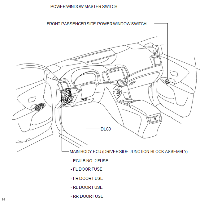
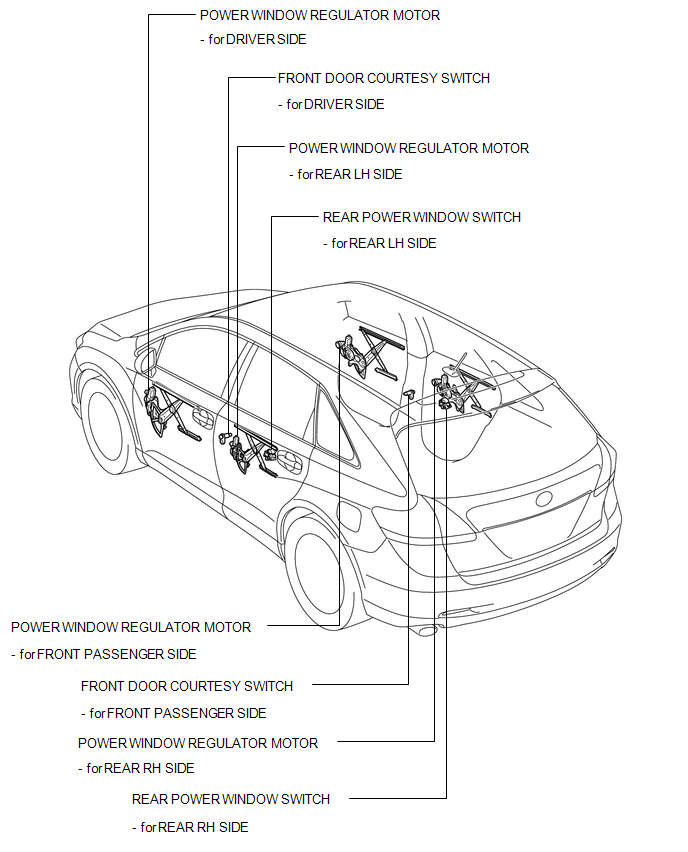
PARTS LOCATION
ILLUSTRATION
ILLUSTRATION
 Precaution
PRECAUTION
1. EXPRESSIONS OF IGNITION SWITCH
(a) The type of ignition switch used on this model differs according to the specifications
of the vehicle. The expressions listed in the table below ar ...
 System Diagram
SYSTEM DIAGRAM
Communication Table
Transmitting ECU
Receiving ECU
Signal
Communication Method
Power window regulator master switch ass ...
Other materials about Toyota Venza:
Replacement
REPLACEMENT
PROCEDURE
1. REPLACE INTAKE VALVE GUIDE BUSH
(a) Heat the cylinder head to approximately 80 to 100°C (176 to 212°F).
(b) Place the cylinder head on wooden blocks.
(c) Using SST and a hammer, tap out the valve guide bush.
SST: 0 ...
Steering Lock Motor Drive Power Circuit
DESCRIPTION
The steering lock ECU (steering lock actuator assembly) is connected to the power
management control ECU. The steering lock ECU (steering lock actuator assembly)
cannot activate the motor unless it receives permission signals from both ECUs.
...
Startability Malfunction (P1604)
DESCRIPTION
This DTC is stored when the engine does not start even though the STA signal
is input or when the engine takes a long time to start, and when the engine speed
is low or the engine stalls just after the engine starts.
Using the Techstream, the ...

0.1185