Toyota Venza: System Diagram
SYSTEM DIAGRAM
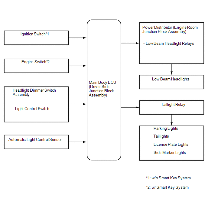
1. AUTOMATIC LIGHT CONTROL SYSTEM
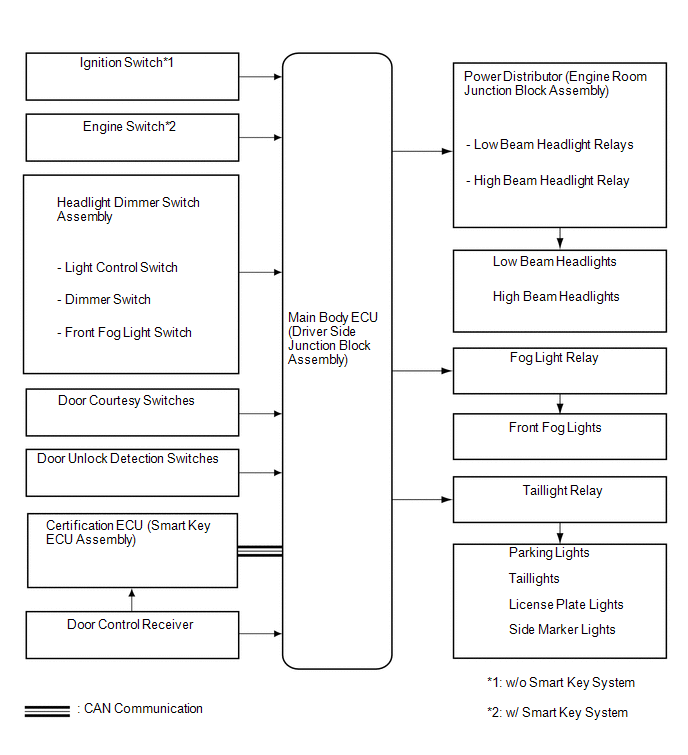
2. LIGHT AUTO TURN-OFF SYSTEM
 Communication Table
|
Transmitter |
Receiver |
Line |
Data Name |
|---|---|---|---|
|
Certification ECU (Smart Key ECU Assembly) |
Main Body ECU (Driver Side Junction Block Assembly) |
CAN |
Wireless Door Lock Signal |
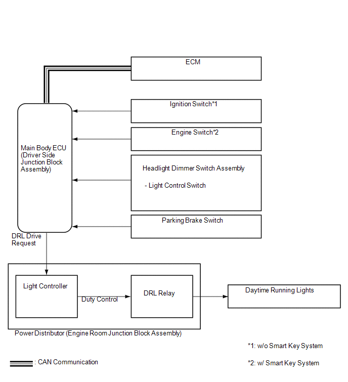
3. DAYTIME RUNNING LIGHT SYSTEM
 Communication Table
|
Transmitter |
Receiver |
Line |
Data Name |
|---|---|---|---|
|
ECM |
Main Body ECU (Driver Side Junction Block Assembly) |
CAN |
Engine RPM Data |
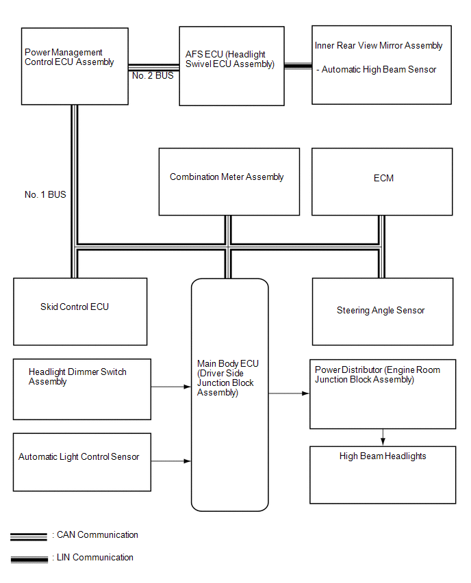
4. AUTOMATIC HIGH BEAM SYSTEM
 Communication Table
|
Transmitter |
Receiver |
Line |
Data Name |
|---|---|---|---|
|
Inner Rear View Mirror Assembly |
AFS ECU (Headlight Swivel ECU Assembly) |
LIN |
High Beam ON Request |
|
Steering Angle Sensor |
AFS ECU (Headlight Swivel ECU Assembly) |
CAN |
Data Continuity (Valid/Invalid) Flag |
|
+B Disconnection |
|||
|
Sensor Error |
|||
|
Zero Point Memory Invalid/Valid Inside Sensor |
|||
|
Memorized Zero Point Value Inside Sensor |
|||
|
Steering Signal |
|||
|
Skid Control ECU |
AFS ECU (Headlight Swivel ECU Assembly) |
CAN |
Front Right Wheel Speed Sensor Error Flag |
|
Front Right Wheel Speed |
|||
|
ECM |
AFS ECU (Headlight Swivel ECU Assembly) |
CAN |
Shift Position R Signal |
|
Main Body ECU (Driver Side Junction Block Assembly) |
AFS ECU (Headlight Swivel ECU Assembly) |
CAN |
Automatic High Beam Enable |
|
Main Body ECU (Driver Side Junction Block Assembly) |
Combination Meter Assembly |
CAN |
Automatic High Beam Indicator |
|
AFS ECU (Headlight Swivel ECU Assembly) |
Main Body ECU (Driver Side Junction Block Assembly) |
CAN |
Automatic High Beam Request |
|
Failure of Automatic High Beam Sensor |
|||
|
Condition of Automatic High Beam Sensor |
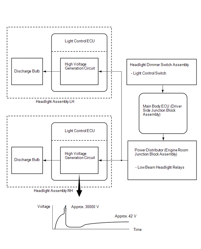
5. HID HEADLIGHT SYSTEM
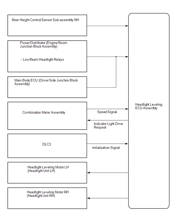
6. AUTOMATIC HEADLIGHT BEAM LEVEL CONTROL SYSTEM
7. DOOR MIRROR FOOT LIGHT SYSTEM
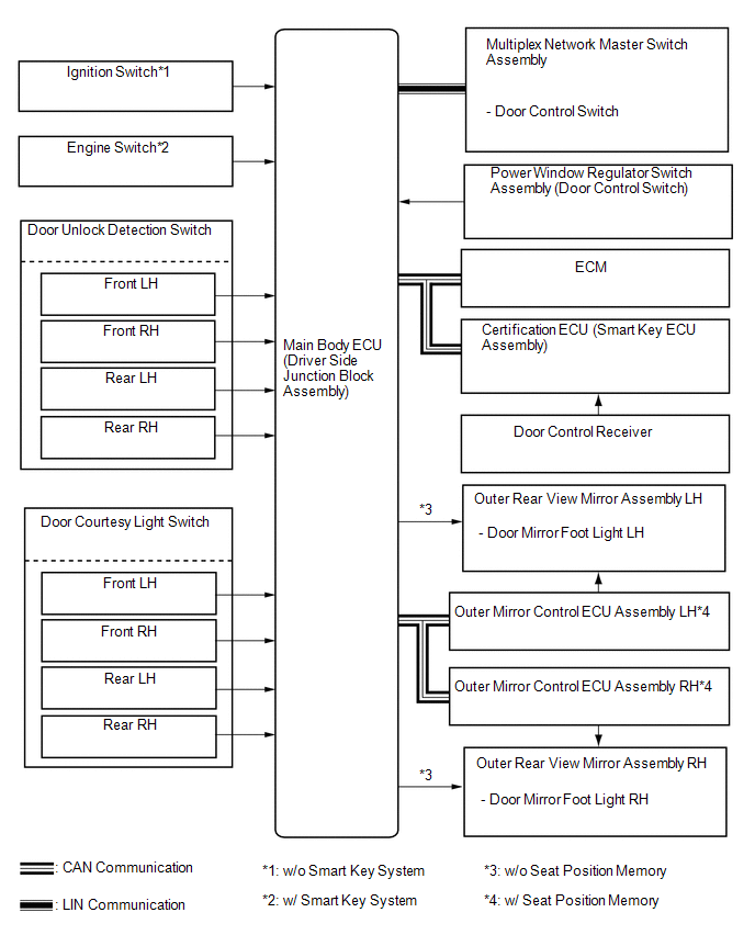 Communication Table
|
Transmitter |
Receiver |
Line |
Data Name |
|---|---|---|---|
|
Main Body ECU (Driver Side Junction Block Assembly) |
Outer Rear View Mirror ECU Assembly LH |
CAN |
Door Mirror Foot Light On Demand Signal |
|
ECM |
Main Body ECU (Driver Side Junction Block Assembly) |
CAN |
Shift Position P Signal |
|
Certification ECU (Smart Key ECU Assembly) |
Main Body ECU (Driver Side Junction Block Assembly) |
CAN |
Wireless Door Lock Signal |
|
Main Body ECU (Driver Side Junction Block Assembly) |
Outer Rear View Mirror ECU Assembly RH |
CAN |
Door Mirror Foot Light On Demand Signal |
 System Description
SYSTEM DESCRIPTION
1. AUTOMATIC LIGHT CONTROL SYSTEM
When the light control switch is in the AUTO position, the automatic light control
system detects ambient light levels and controls the low bea ...
 How To Proceed With Troubleshooting
CAUTION / NOTICE / HINT
HINT:
Use the following procedure to troubleshoot the lighting system.
*: Use the Techstream.
PROCEDURE
1.
VEHICLE BROUGHT TO WO ...
Other materials about Toyota Venza:
Idle Control System Malfunction (P0505)
DESCRIPTION
The idle speed is controlled by the electronic throttle control system. The electronic
throttle control system is comprised of: 1) the one-valve-type throttle body; 2)
the throttle actuator, which operates the throttle valve; 3) the throttle p ...
Reassembly
REASSEMBLY
PROCEDURE
1. INSTALL STIFFENING CRANKCASE RING PIN
NOTICE:
It is not necessary to remove the ring pin unless it is being replaced.
(a) Using a plastic-faced hammer, tap in 2 new ring pins until they stop.
Text in Illustration
...
Removal
REMOVAL
CAUTION / NOTICE / HINT
HINT:
Use the same procedure for the RH side and LH side.
The procedure listed below is for the LH side.
PROCEDURE
1. DISCONNECT CABLE FROM NEGATIVE BATTERY TERMINAL
CAUTION:
Wait at least 90 seconds aft ...

0.1147