Toyota Venza: Removal
REMOVAL
PROCEDURE
1. REMOVE REAR DOOR SCUFF PLATE
.gif)
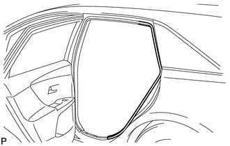
2. DISCONNECT REAR DOOR OPENING TRIM WEATHERSTRIP
|
(a) Remove the rear part of the rear door opening trim weatherstrip to the extent that allows removal of the deck trim side panel assembly and roof side inner garnish assembly. |
|
3. REMOVE TONNEAU COVER ASSEMBLY (w/ Tonneau Cover)
4. REMOVE DECK BOARD ASSEMBLY
5. REMOVE NO. 3 DECK BOARD SUB-ASSEMBLY
6. REMOVE DECK SIDE TRIM BOX LH
7. REMOVE NO. 2 DECK BOARD SUB-ASSEMBLY
8. REMOVE DECK SIDE TRIM BOX RH
9. REMOVE NO. 1 DECK BOARD
10. REMOVE REAR SEAT SUB FLOOR PANEL ASSEMBLY
11. REMOVE REAR FLOOR FINISH PLATE
12. REMOVE REAR SEAT HEADREST ASSEMBLY (for LH Side)
13. REMOVE REAR SEAT INNER TRACK BRACKET COVER (for LH Side)
14. REMOVE REAR SEAT OUTER TRACK BRACKET COVER (for LH Side)
15. DISCONNECT REAR SEAT NO. 2 RECLINING CONTROL CABLE SUB-ASSEMBLY (for LH Side)
16. REMOVE REAR SEAT ASSEMBLY LH (for LH Side)
17. REMOVE REAR SEAT HEADREST ASSEMBLY (for RH Side)
18. REMOVE REAR SEAT CENTER HEADREST ASSEMBLY (for RH Side)
19. REMOVE REAR SEAT INNER TRACK BRACKET COVER (for RH Side)
20. REMOVE REAR SEAT OUTER TRACK BRACKET COVER (for RH Side)
21. DISCONNECT REAR SEAT RECLINING CONTROL CABLE SUB-ASSEMBLY (for RH Side)
22. REMOVE REAR SEAT ASSEMBLY RH (for RH Side)
23. REMOVE RECLINING REMOTE CONTROL BEZEL
24. REMOVE LUGGAGE HOLD BELT STRIKER ASSEMBLY
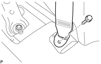
25. DISCONNECT REAR SEAT OUTER BELT ASSEMBLY
|
(a) Remove the bolt and disconnect the floor end of the rear seat outer belt assembly. |
|
26. REMOVE DECK TRIM SIDE PANEL ASSEMBLY LH (for LH Side)
27. REMOVE DECK TRIM SIDE PANEL ASSEMBLY RH (for RH Side)
28. REMOVE ROOF SIDE INNER GARNISH ASSEMBLY
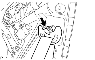
29. REMOVE REAR SEAT OUTER BELT ASSEMBLY
|
(a) Remove the bolt and disconnect the shoulder anchor of the rear seat outer belt assembly. |
|
|
(b) Remove the 2 bolts. |
|
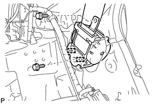
(c) Disengage the 2 guides and remove the rear seat outer belt assembly
 Components
COMPONENTS
ILLUSTRATION
ILLUSTRATION
ILLUSTRATION
ILLUSTRATION
ILLUSTRATION
ILLUSTRATION
...
 Installation
INSTALLATION
PROCEDURE
1. INSTALL REAR SEAT OUTER BELT ASSEMBLY
(a) Engage the 2 guides.
(b) Install the rear seat outer belt assembly wit ...
Other materials about Toyota Venza:
Inspection
INSPECTION
PROCEDURE
1. INSPECT SHIFT SOLENOID VALVE SL
(a) Measure the resistance according to the value(s) in the table below.
Text in Illustration
*1
Shift Solenoid Valve SL
Standard Re ...
Lost Communication with ECM (U0100-U0142,U0155)
DESCRIPTION
DTC No.
DTC Detecting Condition
Trouble Area
U0100
No communication with ECM
CAN communication system
ECM
U0131
No commu ...
Rear Airbag Sensor LH Circuit Malfunction (B1635/24)
DESCRIPTION
The side collision sensor LH circuit (to determine deployment of the front seat
side airbag assembly LH and curtain shield airbag assembly LH) is composed of the
center airbag sensor assembly, rear airbag sensor LH and side airbag sensor LH.
...

0.1441