Toyota Venza: System Diagram
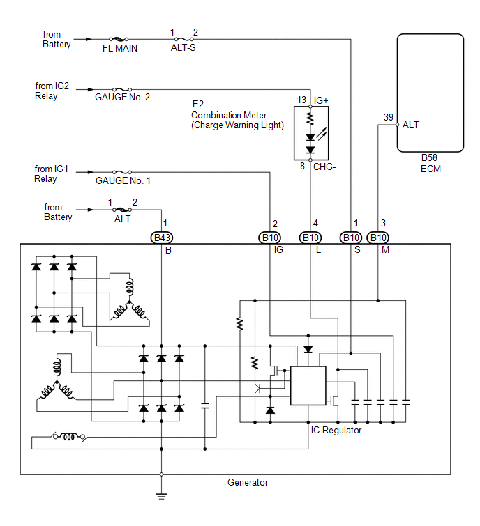
SYSTEM DIAGRAM
 Parts Location
PARTS LOCATION
ILLUSTRATION
ILLUSTRATION
...
 On-vehicle Inspection
ON-VEHICLE INSPECTION
PROCEDURE
1. CHECK BATTERY CONDITION
NOTICE:
If the battery is weak or if the engine is difficult to start, perform the following
procedure.
(a) Check the battery for dama ...
Other materials about Toyota Venza:
Diagnosis System
DIAGNOSIS SYSTEM
1. DESCRIPTION
(a) When troubleshooting On-Board Diagnostic (OBD II) vehicles, the vehicle must
be connected to the OBD II scan tool (complying with SAE J1987). Various data output
from the vehicle TCM can then be read.
(b) OBD II regul ...
On-vehicle Inspection
ON-VEHICLE INSPECTION
PROCEDURE
1. INSPECT ENGINE COOLANT
See page
2. INSPECT ENGINE OIL
See page
3. INSPECT BATTERY
See page
4. INSPECT AIR CLEANER FILTER ELEMENT SUB-ASSEMBLY
(a) Remove the air cleaner filter element sub-assembly.
(b) Visuall ...
Internal Control Module Monitoring Processor Performance (P060A)
MONITOR DESCRIPTION
The main CPU and sub CPU of the ECM perform data communication between each other.
The main CPU monitors the communications and WDC pulses from the sub CPU. When the
signal malfunctions below are detected, the DTC is output.
...

0.1501