Toyota Venza: Parts Location
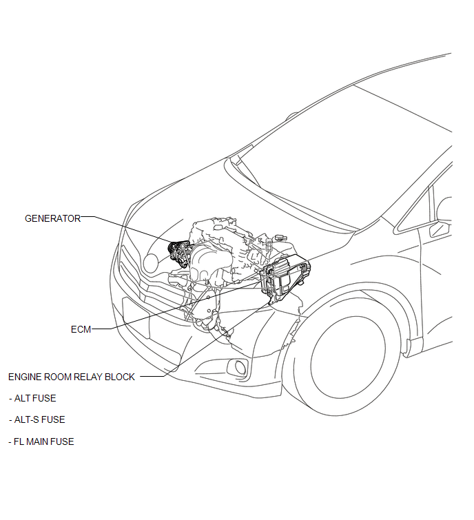
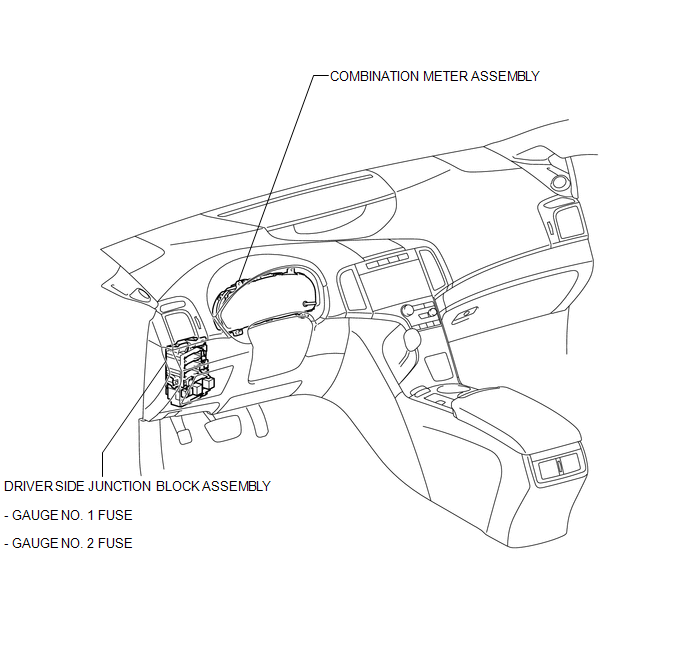
PARTS LOCATION
ILLUSTRATION
ILLUSTRATION
 Precaution
PRECAUTION
1. Check that the battery cables are connected to the correct terminals.
2. Disconnect the battery cables when the battery is given a quick charge.
3. Do not perform tests with a high vo ...
 System Diagram
SYSTEM DIAGRAM
...
Other materials about Toyota Venza:
Inspection
INSPECTION
PROCEDURE
1. INSPECT PRELOAD
(a) Using SST and a torque wrench, measure the preload of the backlash
between the driven pinion and ring gear.
SST: 09326-20011
Preload (at Starting):
Item
P ...
Removal
REMOVAL
PROCEDURE
1. REMOVE INSTRUMENT PANEL REINFORCEMENT ASSEMBLY WITH AIR CONDITIONING UNIT
(See page )
2. REMOVE COOL AIR INTAKE DUCT SEAL
3. REMOVE INLET NO. 2 AIR CLEANER
4. REMOVE AIR CLEANER CAP WITH HOSE
5. REMOVE AIR CLEANER CASE
...
Ignition Coil And Spark Plug
Components
COMPONENTS
ILLUSTRATION
Removal
REMOVAL
PROCEDURE
1. REMOVE NO. 1 ENGINE COVER SUB-ASSEMBLY
2. REMOVE IGNITION COIL ASSEMBLY
(a) Disconnect the 4 ignition coil assembly connectors.
(b) Remove the 4 bolts and 4 ignition c ...

0.1266