Toyota Venza: System Diagram
SYSTEM DIAGRAM
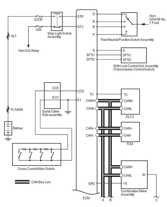
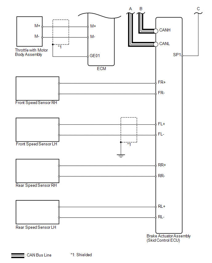 Communication Table
|
Sender |
Receiver |
Signal |
Line |
|---|---|---|---|
|
ECM |
Combination Meter ECU |
|
CAN |
|
ECM |
TCM |
Shift up/down request signal |
CAN |
|
TCM |
ECM |
Shift up/down response signal |
CAN |
 Parts Location
PARTS LOCATION
ILLUSTRATION
ILLUSTRATION
...
 System Description
SYSTEM DESCRIPTION
1. CRUISE CONTROL SYSTEM
This system is controlled by the ECM, and is activated by the throttle position
sensor and motor. The ECM controls the following functions: ON-OFF, - SE ...
Other materials about Toyota Venza:
Throttle Actuator Control Motor Circuit Low (P2102,P2103)
DESCRIPTION
The throttle actuator is operated by the ECM and opens and closes the throttle
valve using gears.
The opening angle of the throttle valve is detected by the throttle position
sensor, which is mounted on the throttle body. The throttle positio ...
Ignition Coil "A" Primary / Secondary Circuit (P0351-P0354)
DESCRIPTION
HINT:
These DTCs indicate malfunctions relating to the primary circuit.
If DTC P0351 is output, check the No. 1 ignition coil circuit.
If DTC P0352 is output, check the No. 2 ignition coil circuit.
If DTC P0353 is output, c ...
Driver Side Solar Sensor Short Circuit (B14A2)
DESCRIPTION
The solar sensor is installed on the upper side of the instrument panel. It detects
sunlight to control air conditioning AUTO mode. The output voltage from the solar
sensor varies in accordance with the amount of sunlight. When the amount of ...

0.1155