Toyota Venza: Parts Location
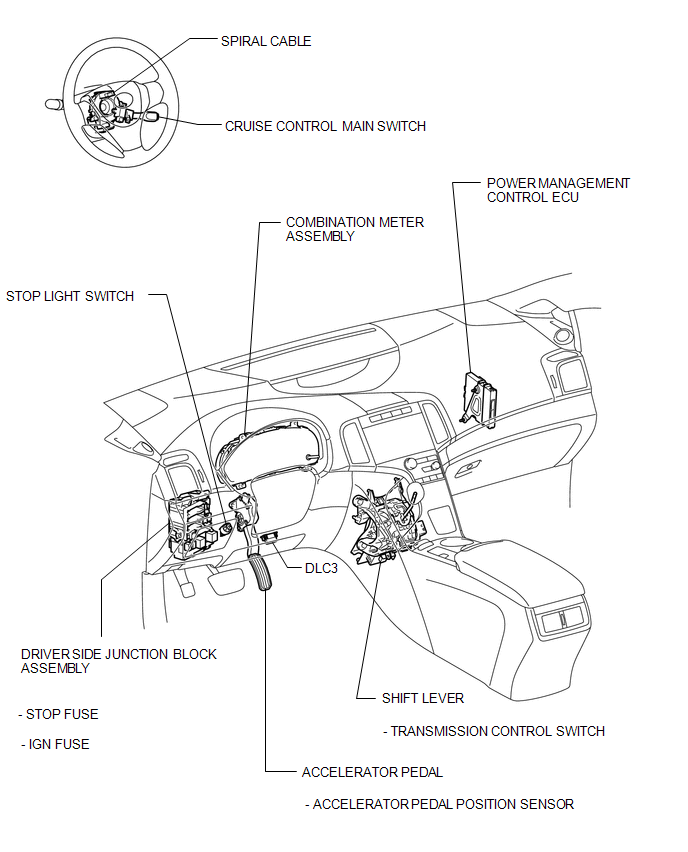
PARTS LOCATION
ILLUSTRATION

ILLUSTRATION
 Precaution
PRECAUTION
NOTICE:
When disconnecting the cable from the negative (-) battery terminal, initialize
the following systems after the cable is reconnected.
System Name
See Proc ...
 System Diagram
SYSTEM DIAGRAM
Communication Table
Sender
Receiver
Signal
Line
ECM
Combination Meter ECU
CRUISE main ...
Other materials about Toyota Venza:
Disassembly
DISASSEMBLY
PROCEDURE
1. REMOVE BREATHER PLUG HOSE
(a) Using a screwdriver, remove the No. 2 breather plug (ATM) from the
transaxle case sub-assembly.
(b) Using a screwdriver, remove ...
Pressure Control Solenoid "A" Electrical (Shift Solenoid Valve SL1) (P0748)
DESCRIPTION
Changing from 1st to 6th is performed by the TCM turning shift solenoid valves
SL1, SL2, SL3, SL4 and SL on and off. If an open or short circuit occurs in any
of the shift solenoid valves, the TCM controls the remaining normal shift solenoid
...
Front Passenger Side Door Entry Unlock Function does not Operate
DESCRIPTION
If the front passenger door entry lock function operates normally, but its entry
unlock function does not, this means that the request code from the front passenger
door is being output normally. In this case, a malfunction in the touch sensor ...

0.1293