Toyota Venza: Steering Pad Switch Circuit
DESCRIPTION
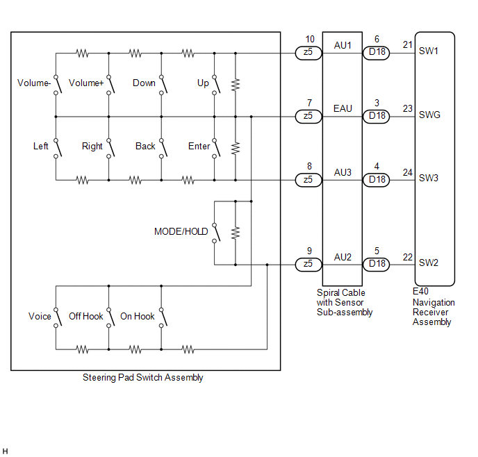
This circuit sends an operation signal from the steering pad switch assembly to the navigation receiver assembly.
If there is an open in the circuit, the audio system cannot be operated using the steering pad switch assembly.
If there is a short in the circuit, the same condition as when a switch is continuously depressed occurs.
Therefore, the navigation receiver assembly cannot be operated using the steering pad switch assembly, also the navigation receiver assembly itself will not function.
WIRING DIAGRAM
CAUTION / NOTICE / HINT
NOTICE:
The vehicle is equipped with a Supplemental Restraint System (SRS) which includes
components such as airbags. Before servicing (including removal or installation
of parts), be sure to read the precaution for Supplemental Restraint System (See
page .gif) ).
).
PROCEDURE
|
1. |
CHECK HARNESS AND CONNECTOR (STEERING PAD SWITCH SIGNAL) |
(a) Disconnect the E40 navigation receiver assembly connector.
(b) Measure the resistance according to the value(s) in the table below.
Standard Resistance:
|
Tester Connection |
Condition |
Specified Condition |
|---|---|---|
|
E40-21 (SW1) - E40-23 (SWG) |
No switch pushed |
95 to 105 kΩ |
|
Up switch pushed |
Below 2.5 Ω |
|
|
Down switch pushed |
313 to 345 Ω |
|
|
Volume+ switch pushed |
950 to 1050 Ω |
|
|
Volume- switch pushed |
2955 to 3265 Ω |
|
|
E40-22 (SW2) - E40-23 (SWG) |
No switch pushed |
95 to 105 kΩ |
|
MODE/HOLD switch pushed |
Below 2.5 Ω |
|
|
On hook switch pushed |
313 to 345 Ω |
|
|
Off hook switch pushed |
950 to 1050 Ω |
|
|
Voice switch pushed |
2955 to 3265 Ω |
|
|
E40-24 (SW3) - E40-23 (SWG) |
No switch pushed |
95 to 105 kΩ |
|
Enter switch pushed |
Below 2.5 Ω |
|
|
Back switch pushed |
313 to 345 Ω |
|
|
Right switch pushed |
950 to 1050 Ω |
|
|
Left switch pushed |
2955 to 3265 Ω |
| OK | .gif) |
PROCEED TO NEXT SUSPECTED AREA SHOWN IN PROBLEM SYMPTOMS TABLE |
|
.gif)
|
2. |
INSPECT STEERING PAD SWITCH ASSEMBLY |
(a) Remove the steering pad switch assembly (See page
).
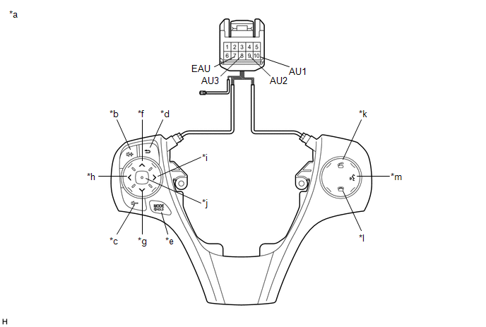 Text in Illustration
|
*a |
Component without harness connected (Steering Pad Switch Assembly) |
*b |
Volume+ |
|
*c |
Volume- |
*d |
Back |
|
*e |
MODE/HOLD |
*f |
Up |
|
*g |
Down |
*h |
Left |
|
*i |
Right |
*j |
Enter |
|
*k |
Off hook |
*l |
On hook |
|
*m |
Voice |
- |
- |
(b) Measure the resistance according to the value(s) in the table below.
Standard Resistance:
|
Tester Connection |
Condition |
Specified Condition |
|---|---|---|
|
10 (AU1) - 7 (EAU) |
No switch pushed |
95 to 105 kΩ |
|
Up switch pushed |
Below 2.5 Ω |
|
|
Down switch pushed |
313 to 345 Ω |
|
|
Volume+ switch pushed |
950 to 1050 Ω |
|
|
Volume- switch pushed |
2955 to 3265 Ω |
|
|
9 (AU2) - 7 (EAU) |
No switch pushed |
95 to 105 kΩ |
|
MODE/HOLD switch pushed |
Below 2.5 Ω |
|
|
On hook switch pushed |
313 to 345 Ω |
|
|
Off hook switch pushed |
950 to 1050 Ω |
|
|
Voice switch pushed |
2955 to 3265 Ω |
|
|
8 (AU3) - 7 (EAU) |
No switch pushed |
95 to 105 kΩ |
|
Enter switch pushed |
Below 2.5 Ω |
|
|
Back switch pushed |
313 to 345 Ω |
|
|
Right switch pushed |
950 to 1050 Ω |
|
|
Left switch pushed |
2955 to 3265 Ω |
| NG | |
REPLACE STEERING PAD SWITCH ASSEMBLY |
|
|
3. |
INSPECT SPIRAL CABLE WITH SENSOR SUB-ASSEMBLY |
(a) Remove the spiral cable with sensor sub-assembly (See page
).
|
(b) Measure the resistance according to the value(s) in the table below. Standard Resistance:
|
|
.png)
(c) After setting the spiral cable with sensor sub-assembly to the center position, rotate the spiral cable with sensor sub-assembly 2.5 times clockwise. Then while rotating the spiral cable with sensor sub-assembly 5 times counterclockwise, measure the resistance according to the value(s) in the table below.
Standard Resistance:
|
Tester Connection |
Condition |
Specified Condition |
|---|---|---|
|
z5-7 (EAU) - D18-3 (EAU) |
Always |
3 Ω or less |
|
z5-10 (AU1) - D18-6 (AU1) |
Always |
3 Ω or less |
|
z5-9 (AU2) - D18-5 (AU2) |
Always |
3 Ω or less |
|
z5-8 (AU3) - D18-4 (AU3) |
Always |
3 Ω or less |
NOTICE:
- Press and hold the lock located in the center of the spiral cable with sensor sub-assembly to rotate the spiral cable with sensor sub-assembly.
- The spiral cable with sensor sub-assembly is an important part of the SRS airbag system. Incorrect removal or installation of the spiral cable with sensor sub-assembly may prevent the airbag from deploying.
- As the spiral cable with sensor sub-assembly may break, do not rotate the spiral cable with sensor sub-assembly more than the specified amount.
|
*a |
Component without harness connected (Spiral Cable with Sensor Sub-assembly) |
|
*b |
Steering Pad Switch Assembly Side |
|
*c |
Vehicle Side |
| OK | |
REPAIR OR REPLACE HARNESS OR CONNECTOR (NAVIGATION RECEIVER ASSEMBLY - SPIRAL CABLE WITH SENSOR SUB-ASSEMBLY) |
| NG | |
REPLACE SPIRAL CABLE WITH SENSOR SUB-ASSEMBLY |
 Illumination Circuit
DESCRIPTION
Power is supplied to the navigation receiver assembly and steering pad switch
assembly illumination when the light control switch is in the tail or head position.
WIRING DIAGRAM
CAU ...
 Speaker Circuit
DESCRIPTION
for 6 Speakers:
If there is a short in a speaker circuit, the navigation receiver assembly detects
it and stops output to the speakers.
Thus sound cannot be heard from the speakers ev ...
Other materials about Toyota Venza:
Removal
REMOVAL
PROCEDURE
1. DISCONNECT CABLE FROM NEGATIVE BATTERY TERMINAL
NOTICE:
When disconnecting the cable, some systems need to be initialized after the cable
is reconnected (See page ).
2. REMOVE NO. 1 ENGINE COVER SUB-ASSEMBLY
3. REMOVE COOL AIR ...
If your vehicle has to be stopped in an emergency
Only in an emergency, such as if it becomes impossible to stop the vehicle
in the normal way, stop the vehicle using the following procedure:
Steadily step on the brake pedal
with both feet and firmly depress it.
Do not pump the brake pedal repeatedly a ...
Terminals Of Ecu
TERMINALS OF ECU
1. CHECK OUTER MIRROR CONTROL ECU ASSEMBLY (DRIVER DOOR)
(a) Disconnect the I13 connector.
(b) Measure the voltage and resistance according to the value(s) in the table
below.
HINT:
Measure the values on the wire harness side with the ...

0.1309