Toyota Venza: Sliding Roof ECU Communication Stop (B1273)
DESCRIPTION
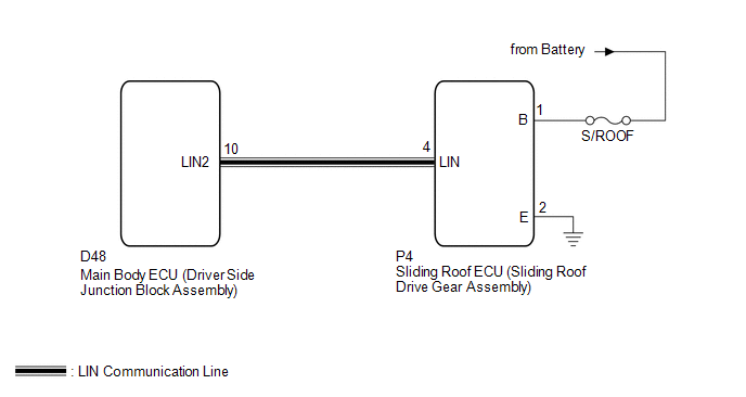
This DTC is stored when LIN communication between the sliding roof ECU (sliding roof drive gear sub-assembly) and main body ECU (driver side junction block assembly) stops for more than 10 seconds.
|
DTC No. |
DTC Detection Condition |
Trouble Area |
|---|---|---|
|
B1273 |
No communication between the sliding roof ECU (sliding roof drive gear sub-assembly) and main body ECU (driver side junction block assembly) for more than 10 seconds. |
|
WIRING DIAGRAM
CAUTION / NOTICE / HINT
NOTICE:
- When the sliding roof ECU (sliding roof drive gear sub-assembly) is
replaced or removed and reinstalled, it requires initialization (See page
.gif) ).
). - When using the Techstream to troubleshoot with the ignition switch off:
Connect the Techstream to the DLC3, and turn the courtesy switch on and off at 1.5-second intervals until communication between the Techstream and vehicle begins.
PROCEDURE
|
1. |
CHECK HARNESS AND CONNECTOR (SLIDING ROOF ECU - BATTERY AND BODY GROUND) |
|
(a) Disconnect the P4 ECU connector. |
|
(b) Measure the resistance and voltage according to the value(s) in the table below.
Standard Resistance:
|
Tester Connection |
Condition |
Specified Condition |
|---|---|---|
|
P4-2 (E) - Body ground |
Always |
Below 1 Ω |
Standard Voltage:
|
Tester Connection |
Condition |
Specified Condition |
|---|---|---|
|
P4-1 (B) - Body ground |
Always |
11 to 14 V |
|
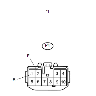
*1 |
Front view of wire harness connector (to Sliding Roof ECU (Sliding Roof Drive Gear Sub-assembly)) |
| NG | .gif) |
REPAIR OR REPLACE HARNESS OR CONNECTOR |
|
.gif)
|
2. |
CHECK HARNESS AND CONNECTOR (MAIN BODY ECU - SLIDING ROOF ECU) |
|
(a) Disconnect the D48 ECU connector. |
|
(b) Measure the resistance according to the value(s) in the table below.
Standard Resistance:
|
Tester Connection |
Condition |
Specified Condition |
|---|---|---|
|
D48-10 (LIN2) - P4-4 (LIN) |
Always |
Below 1 Ω |
|
P4-4 (LIN) - Body ground |
Always |
10 kΩ or higher |
|
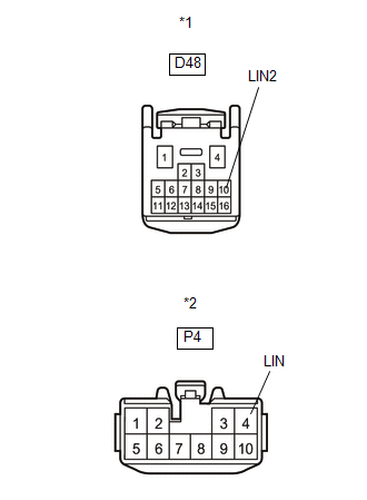
*1 |
Front view of wire harness connector (to Main Body ECU (Driver Side Junction Block Assembly)) |
|
*2 |
Front view of wire harness connector (to Sliding Roof ECU (Sliding Roof Drive Gear Sub-assembly)) |
| NG | |
REPAIR OR REPLACE HARNESS OR CONNECTOR |
|
|
3. |
REPLACE SLIDING ROOF ECU (SLIDING ROOF DRIVE GEAR SUB-ASSEMBLY) |
(a) Replace the sliding roof ECU (sliding roof drive gear sub-assembly) (See
page ).
|
|
4. |
CHECK DTC OUTPUT |
(a) Clear the DTC (See page ).
(b) Recheck for DTCs.
OK:
DTC B1273 is not output.
| OK | |
END (SLIDING ROOF ECU WAS DEFECTIVE) |
| NG | |
REPLACE MAIN BODY ECU (DRIVER SIDE JUNCTION BLOCK ASSEMBLY) |
 Driver Side Door ECU Communication Stop (B2321)
DESCRIPTION
This DTC is stored when LIN communication between the power window regulator
motor assembly (for driver side) and main body ECU (driver side junction block assembly)
stops for more th ...
 LIN Communication Master Malfunction (B2287)
DESCRIPTION
This DTC is stored when there is an open, short or ECU communication malfunction
between the power management control ECU and certification ECU (smart key ECU assembly).
DTC ...
Other materials about Toyota Venza:
Installation
INSTALLATION
CAUTION / NOTICE / HINT
HINT:
Use the same procedure for the RH side and LH side.
The procedure listed below is for the LH side.
PROCEDURE
1. INSTALL REAR AXLE HUB AND BEARING ASSEMBLY
(a) Apply a total of 0.1 to 0.3g (0.00 ...
Automatic High Beam System (B124B)
DESCRIPTION
The DTC is stored when the main body ECU (driver side junction block assembly)
detects malfunctions in the automatic high beam system.
DTC No.
DTC Detection Condition
Trouble Area
B124B
...
Brake Pedal Load Sensing Switch (C1267/67)
DESCRIPTION
The brake pedal load sensing switch is turned on when the brake pedal is depressed
with force exceeding a predetermined level.
The skid control ECU detects if the brake pedal is depressed or not via this
circuit.
DTC Code
...

0.1681