Toyota Venza: Short in Driver Side Knee Airbag Squib Circuit (B1860/64-B1863/64)
DESCRIPTION
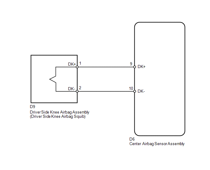
The driver side knee airbag squib circuit consists of the center airbag sensor assembly and driver side knee airbag assembly.
The center airbag sensor assembly uses this circuit to deploy the airbag when deployment conditions are met.
These DTCs are stored when a malfunction is detected in the driver side knee airbag squib circuit.
|
DTC No. |
DTC Detection Condition |
Trouble Area |
|---|---|---|
|
B1860/64 |
|
|
|
B1861/64 |
|
|
|
B1862/64 |
|
|
|
B1863/64 |
|
|
WIRING DIAGRAM
CAUTION / NOTICE / HINT
HINT:
- Perform the simulation method by selecting check mode (Signal Check)
using the Techstream (See page
.gif) ).
).
- After selecting check mode (Signal Check), perform the simulation method
by wiggling each connector of the airbag system or driving the vehicle on
a city or rough road (See page ).
PROCEDURE
|
1. |
CHECK CONNECTORS |
|
(a) Turn the ignition switch off. |
|
(b) Disconnect the cable from the negative (-) battery terminal, and wait for at least 90 seconds.
(c) Check that the connectors are properly connected to the driver side knee airbag assembly and center airbag sensor assembly.
OK:
The connectors are properly connected.
HINT:
If the connectors are not connected securely, reconnect the connectors and proceed to the next inspection.
(d) Disconnect the connectors from the driver side knee airbag assembly and center airbag sensor assembly.
(e) Check that the terminals of the connectors are not damaged.
OK:
The terminals are not deformed or damaged.
(f) Check that the instrument panel wire connector (on the driver side knee airbag assembly side) is not damaged.
OK:
The lock button is not disengaged, and the claw of the lock is not deformed or damaged.
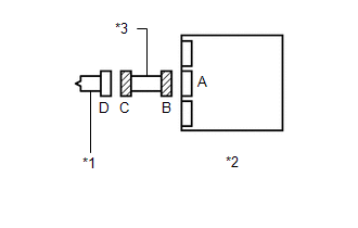
(g) Check that the short spring for the instrument panel wire with the activation prevention mechanism are not deformed or damaged.
OK:
The short spring is not deformed or damaged.
Text in Illustration|
*1 |
Driver Side Knee Airbag Squib |
|
*2 |
Center Airbag Sensor Assembly |
|
*3 |
Instrument Panel Wire |
| NG | .gif) |
REPLACE INSTRUMENT PANEL WIRE |
|
.gif)
|
2. |
CHECK DRIVER SIDE KNEE AIRBAG ASSEMBLY (DRIVER SIDE KNEE AIRBAG SQUIB) |
|
(a) Connect the connector to the center airbag sensor assembly. |
|
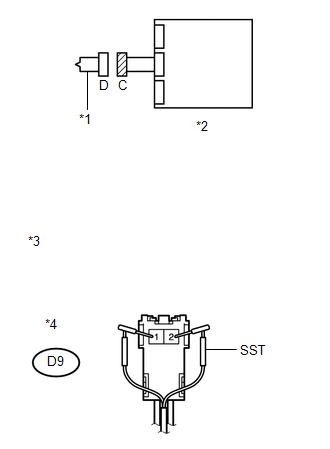
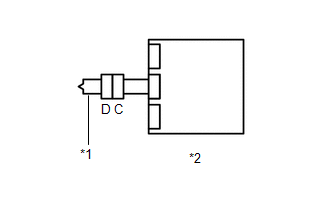
(b) Connect SST (resistance 2.1 Ω) to connector C.
CAUTION:
Never connect an electrical tester to the driver side knee airbag assembly (driver side knee airbag squib) for measurement, as this may lead to a serious injury due to airbag deployment.
NOTICE:
- Do not forcibly insert SST into the terminals of the connector when connecting.
- Insert SST straight into the terminals of the connector.
SST: 09843-18061
(c) Connect the cable to the negative (-) battery terminal.
(d) Turn the ignition switch to ON, and wait for at least 60 seconds.
(e) Clear the DTCs stored in memory (See page
).
(f) Turn the ignition switch off.
(g) Turn the ignition switch to ON, and wait for at least 60 seconds.
(h) Check for DTCs (See page ).
OK:
DTC B1860, B1861, B1862, B1863 or 64 is not output.
Text in Illustration|
*1 |
Driver Side Knee Airbag Squib |
|
*2 |
Center Airbag Sensor Assembly |
|
*3 |
Front view of wire harness connector (to Driver Side Knee Airbag Assembly) |
|
*4 |
Connector C |
HINT:
Codes other than DTCs B1860, B1861, B1862, B1863 and 64 may be output at this time, but they are not related to this check.
| OK | |
REPLACE DRIVER SIDE KNEE AIRBAG ASSEMBLY |
|
|
3. |
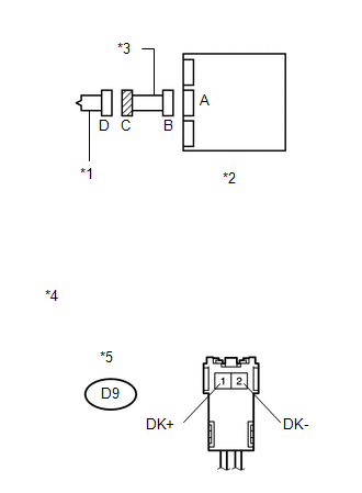
CHECK INSTRUMENT PANEL WIRE (DRIVER SIDE KNEE AIRBAG SQUIB CIRCUIT) |
|
(a) Turn the ignition switch off. |
|
(b) Disconnect the cable from the negative (-) battery terminal, and wait for at least 90 seconds.
(c) Disconnect SST from connector C.
(d) Disconnect the instrument panel wire from the center airbag sensor assembly.
(e) Check for a short to B+ in the circuit.
(1) Connect the cable to the negative (-) battery terminal.
(2) Turn the ignition switch to ON.
(3) Measure the voltage according to the value(s) in the table below.
Standard Voltage:
|
Tester Connection |
Switch Condition |
Specified Condition |
|---|---|---|
|
D9-1 (DK+) - Body ground |
Ignition switch ON |
Below 1 V |
|
D9-2 (DK-) - Body ground |
Ignition switch ON |
Below 1 V |
(f) Check for an open in the circuit.
(1) Turn the ignition switch off.
(2) Disconnect the cable from the negative (-) battery terminal, and wait for at least 90 seconds.
(3) Measure the resistance according to the value(s) in the table below.
Standard Resistance:
|
Tester Connection |
Condition |
Specified Condition |
|---|---|---|
|
D9-1 (DK+) - D9-2 (DK-) |
Always |
Below 1 Ω |
(g) Check for a short to ground in the circuit.
(1) Measure the resistance according to the value(s) in the table below.
Standard Resistance:
|
Tester Connection |
Condition |
Specified Condition |
|---|---|---|
|
D9-1 (DK+) - Body ground |
Always |
1 MΩ or higher |
|
D9-2 (DK-) - Body ground |
Always |
1 MΩ or higher |
(h) Check for a short in the circuit.
(1) Release the activation prevention mechanism built into connector B (See page
).
(2) Measure the resistance according to the value(s) in the table below.
Standard Resistance:
|
Tester Connection |
Condition |
Specified Condition |
|---|---|---|
|
D9-1 (DK+) - D9-2 (DK-) |
Always |
1 MΩ or higher |
|
*1 |
Driver Side Knee Airbag Squib |
|
*2 |
Center Airbag Sensor Assembly |
|
*3 |
Instrument Panel Wire |
|
*4 |
Front view of wire harness connector (to Driver Side Knee Airbag Assembly) |
|
*5 |
Connector C |
| NG | |
REPLACE INSTRUMENT PANEL WIRE |
|
|
4. |
CHECK CENTER AIRBAG SENSOR ASSEMBLY |
|
(a) Restore the released activation prevention mechanism of connector B to the original condition. |
|
(b) Connect the connectors to the driver side knee airbag assembly and center airbag sensor assembly.
(c) Connect the cable to the negative (-) battery terminal.
(d) Turn the ignition switch to ON, and wait for at least 60 seconds.
(e) Clear the DTCs stored in memory (See page
).
(f) Turn the ignition switch off.
(g) Turn the ignition switch to ON, and wait for at least 60 seconds.
(h) Check for DTCs (See page ).
OK:
DTC B1860, B1861, B1862, B1863 or 64 is not output.
Text in Illustration|
*1 |
Driver Side Knee Airbag Squib |
|
*2 |
Center Airbag Sensor Assembly |
HINT:
Codes other than DTCs B1860, B1861, B1862, B1863 and 64 may be output at this time, but they are not related to this check.
| OK | |
USE SIMULATION METHOD TO CHECK |
| NG | |
REPLACE CENTER AIRBAG SENSOR ASSEMBLY |
 Short in Curtain Shield Squib LH Circuit (B1835/58-B1838/58)
DESCRIPTION
The curtain shield squib LH circuit consists of the center airbag sensor assembly
and curtain shield airbag assembly LH.
The center airbag sensor assembly uses this circuit to deploy t ...
 Short in Front Pretensioner Squib RH Circuit (B1900/73-B1903/73)
DESCRIPTION
The front pretensioner squib RH circuit consists of the center airbag sensor
assembly and front seat outer belt assembly RH.
The center airbag sensor assembly uses this circuit to depl ...
Other materials about Toyota Venza:
Electrical Key Oscillator(for Center Floor)
Components
COMPONENTS
ILLUSTRATION
Installation
INSTALLATION
PROCEDURE
1. INSTALL ELECTRICAL KEY OSCILLATOR
(a) Engage the clamp and install the electrical key oscillator.
NOTICE:
Be careful when installing the electrical key osci ...
Camshaft Position Sensor "B" Circuit (Bank 1) (P0365,P0367,P0368)
DESCRIPTION
The camshaft position sensor (EV signal sensor) for the exhaust camshaft consists
of a magnet and MRE (Magneto Resistance Element).
The exhaust camshaft has a timing rotor for the camshaft position sensor. When
the camshaft rotates, changes o ...
Initialization
INITIALIZATION
1. PROCEDURES NECESSARY WHEN BATTERY TERMINAL IS DISCONNECTED/RECONNECTED
Necessary Procedure
Effect / Inoperative Function When Necessary Procedures are not Performed
See Page
Reset back door ...

0.1743