Toyota Venza: Short in Curtain Shield Squib LH Circuit (B1835/58-B1838/58)
DESCRIPTION
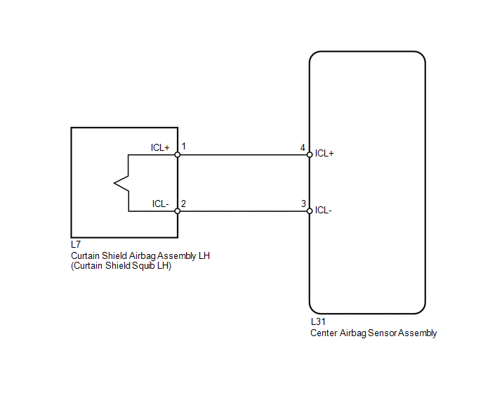
The curtain shield squib LH circuit consists of the center airbag sensor assembly and curtain shield airbag assembly LH.
The center airbag sensor assembly uses this circuit to deploy the airbag when deployment conditions are met.
These DTCs are stored when a malfunction is detected in the curtain shield squib LH circuit.
|
DTC No. |
DTC Detection Condition |
Trouble Area |
|---|---|---|
|
B1835/58 |
|
|
|
B1836/58 |
|
|
|
B1837/58 |
|
|
|
B1838/58 |
|
|
WIRING DIAGRAM
CAUTION / NOTICE / HINT
HINT:
- Perform the simulation method by selecting check mode (Signal Check)
using the Techstream (See page
.gif) ).
).
- After selecting check mode (Signal Check), perform the simulation method
by wiggling each connector of the airbag system or driving the vehicle on
a city or rough road (See page ).
PROCEDURE
|
1. |
CHECK CONNECTORS |
|
(a) Turn the ignition switch off. |
|
.png)
(b) Disconnect the cable from the negative (-) battery terminal, and wait for at least 90 seconds.
(c) Check that the connectors are properly connected to the curtain shield airbag assembly LH and center airbag sensor assembly.
OK:
The connectors are properly connected.
HINT:
If the connectors are not connected securely, reconnect the connectors and proceed to the next inspection.
(d) Disconnect the connectors from the curtain shield airbag assembly LH and center airbag sensor assembly.
(e) Check that the terminals of the connectors are not damaged.
OK:
The terminals are not deformed or damaged.
(f) Check that the floor wire connector (on the curtain shield airbag assembly LH side) is not damaged.
OK:
The lock button is not disengaged, and the claw of the lock is not deformed or damaged.
(g) Check that the short spring for the floor wire with the activation prevention mechanism is not deformed or damaged.
OK:
The short spring is not deformed or damaged.
Text in Illustration|
*1 |
Curtain Shield Squib LH |
|
*2 |
Center Airbag Sensor Assembly |
|
*3 |
Floor Wire |
| NG | .gif) |
REPLACE FLOOR WIRE |
|
.gif)
|
2. |
CHECK CURTAIN SHIELD AIRBAG ASSEMBLY LH (CURTAIN SHIELD LH SQUIB) |
|
(a) Connect the connector to the center airbag sensor assembly. |
|
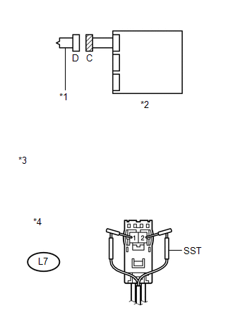
(b) Connect SST (resistance 2.1 Ω) to connector C.
CAUTION:
Never connect an electrical tester to the curtain shield airbag assembly LH (curtain shield squib LH) for measurement, as this may lead to a serious injury due to airbag deployment.
NOTICE:
- Do not forcibly insert SST into the terminals of the connector when connecting.
- Insert SST straight into the terminals of the connector.
SST: 09843-18061
(c) Connect the cable to the negative (-) battery terminal.
(d) Turn the ignition switch to ON, and wait for at least 60 seconds.
(e) Clear the DTCs stored in memory (See page
).
(f) Turn the ignition switch off.
(g) Turn the ignition switch to ON, and wait for at least 60 seconds.
(h) Check for DTCs (See page ).
OK:
DTC B1835, B1836, B1837, B1838 or 58 is not output.
Text in Illustration|
*1 |
Curtain Shield Squib LH |
|
*2 |
Center Airbag Sensor Assembly |
|
*3 |
Front view of wire harness connector (to Curtain Shield Airbag Assembly LH) |
|
*4 |
Connector C |
HINT:
Codes other than DTCs B1835, B1836, B1837, B1838 and 58 may be output at this time, but they are not related to this check.
| OK | |
REPLACE CURTAIN SHIELD AIRBAG ASSEMBLY LH |
|
|
3. |
CHECK FLOOR WIRE (CURTAIN SHIELD SQUIB LH CIRCUIT) |
|
(a) Turn the ignition switch off. |
|
(b) Disconnect the cable from the negative (-) battery terminal, and wait for at least 90 seconds.
(c) Disconnect SST from connector C.
(d) Disconnect the floor wire from the center airbag sensor assembly.
(e) Check for a short to B+ in the circuit.
(1) Connect the cable to the negative (-) battery terminal.
(2) Turn the ignition switch to ON.
(3) Measure the voltage according to the value(s) in the table below.
Standard Voltage:
|
Tester Connection |
Switch Condition |
Specified Condition |
|---|---|---|
|
L7-1 (ICL+) - Body ground |
Ignition switch ON |
Below 1 V |
|
L7-2 (ICL-) - Body ground |
Ignition switch ON |
Below 1 V |
(f) Check for an open in the circuit.
(1) Turn the ignition switch off.
(2) Disconnect the cable from the negative (-) battery terminal, and wait for at least 90 seconds.
(3) Measure the resistance according to the value(s) in the table below.
Standard Resistance:
|
Tester Connection |
Condition |
Specified Condition |
|---|---|---|
|
L7-1 (ICL+) - L7-2 (ICL-) |
Always |
Below 1 Ω |
(g) Check for a short to ground in the circuit.
(1) Measure the resistance according to the value(s) in the table below.
Standard Resistance:
|
Tester Connection |
Condition |
Specified Condition |
|---|---|---|
|
L7-1 (ICL+) - Body ground |
Always |
1 MΩ or higher |
|
L7-2 (ICL-) - Body ground |
Always |
1 MΩ or higher |
(h) Check for a short in the circuit.
(1) Release the activation prevention mechanism built into connector B (See page
).
(2) Measure the resistance according to the value(s) in the table below.
Standard Resistance:
|
Tester Connection |
Condition |
Specified Condition |
|---|---|---|
|
L7-1 (ICL+) - L7-2 (ICL-) |
Always |
1 MΩ or higher |
|
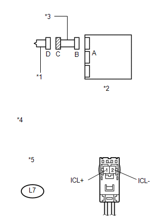
*1 |
Curtain Shield Squib LH |
|
*2 |
Center Airbag Sensor Assembly |
|
*3 |
Floor Wire |
|
*4 |
Front view of wire harness connector (to Curtain Shield Airbag Assembly LH) |
|
*5 |
Connector C |
| NG | |
REPLACE FLOOR WIRE |
|
|
4. |
CHECK CENTER AIRBAG SENSOR ASSEMBLY |
|
(a) Restore the released activation prevention mechanism of connector B to the original condition. |
|
.png)
(b) Connect the connectors to the curtain shield airbag assembly LH and center airbag sensor assembly.
(c) Connect the cable to the negative (-) battery terminal.
(d) Turn the ignition switch to ON, and wait for at least 60 seconds.
(e) Clear the DTCs stored in memory (See page
).
(f) Turn the ignition switch off.
(g) Turn the ignition switch to ON, and wait for at least 60 seconds.
(h) Check for DTCs (See page ).
OK:
DTC B1835, B1836, B1837, B1838 or 58 is not output.
Text in Illustration|
*1 |
Curtain Shield Squib LH |
|
*2 |
Center Airbag Sensor Assembly |
HINT:
Codes other than DTCs B1835, B1836, B1837, B1838 and 58 may be output at this time, but they are not related to this check.
| OK | |
USE SIMULATION METHOD TO CHECK |
| NG | |
REPLACE CENTER AIRBAG SENSOR ASSEMBLY |
 Short in Curtain Shield Squib RH Circuit (B1830/57-B1833/57)
DESCRIPTION
The curtain shield squib RH circuit consists of the center airbag sensor assembly
and curtain shield airbag assembly RH.
The center airbag sensor assembly uses this circuit to deploy t ...
 Short in Driver Side Knee Airbag Squib Circuit (B1860/64-B1863/64)
DESCRIPTION
The driver side knee airbag squib circuit consists of the center airbag sensor
assembly and driver side knee airbag assembly.
The center airbag sensor assembly uses this circuit to dep ...
Other materials about Toyota Venza:
Charge Warning Light Comes ON while Driving
PROCEDURE
1.
CHECK LOCK FUNCTION OF GENERATOR CLUTCH PULLEY
(a) Check the lock function with the pulley installed in the vehicle.
(1) Visually check that the rotor in the generator operates with the engine running.
(b) Check ...
Installation
INSTALLATION
PROCEDURE
1. INSTALL AIR CONDITIONING UNIT ASSEMBLY
(a) Install the air conditioning unit assembly with the 3 nuts.
Torque:
9.8 N·m {100 kgf·cm, 87 in·lbf}
NOTICE:
Tighten the nuts in the order shown in the illustration to install the ...
Image from Camera for Rear View Monitor is Abnormal
DESCRIPTION
The video signal of the rear television camera assembly is transmitted
to the navigation receiver assembly*1 or radio and display receiver assembly*2.
*1: for Navigation System
*2: for Audio and Visual System
WIRING DIAG ...

0.1558