Toyota Venza: Seat Position Sensor
Components
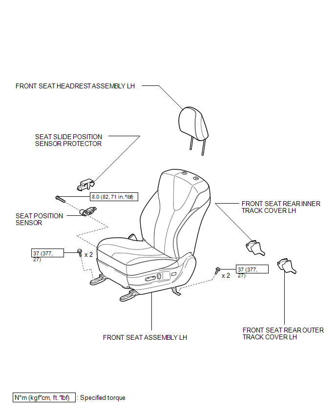
COMPONENTS
ILLUSTRATION
On-vehicle Inspection
ON-VEHICLE INSPECTION
CAUTION / NOTICE / HINT
CAUTION:
Be sure to follow the correct removal and installation procedures of the seat position sensor.
PROCEDURE
1. INSPECT SEAT POSITION SENSOR (VEHICLE NOT INVOLVED IN COLLISION)
(a) Perform a diagnostic system check (See page
.gif) ).
).
2. INSPECT SEAT POSITION SENSOR (VEHICLE INVOLVED IN COLLISION AND AIRBAG HAS NOT DEPLOYED)
(a) Perform a diagnostic system check (See page
).
(b) Visually check for defects with the seat position sensor installed on the vehicle.
(1) The defects are as follows:
- Cracks on the sensor housing
- Dents on the sensor housing
- Chips on the sensor housing
- Cracks or other damage to the connector
OK:
No defects are found.
HINT:
If any of the defects is found, replace the seat position sensor with a new one.
Removal
REMOVAL
PROCEDURE
1. PRECAUTION
CAUTION:
Be sure to read Precaution thoroughly before servicing (See page
.gif) ).
).
2. REMOVE FRONT SEAT ASSEMBLY LH
(See page )
3. REMOVE SEAT POSITION SENSOR
|
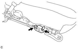
(a) Disconnect the connector. |
|
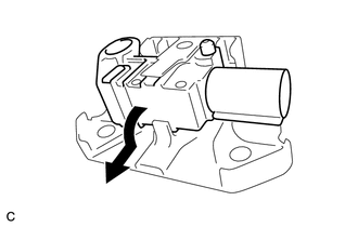
(b) Using a T30 "TORX" socket wrench, remove the "TORX" screw and seat position sensor with the seat slide position sensor protector.
|
(c) Remove the seat position sensor from the seat slide position sensor protector as shown in the illustration. |
|
Installation
INSTALLATION
PROCEDURE
1. INSTALL SEAT POSITION SENSOR
|
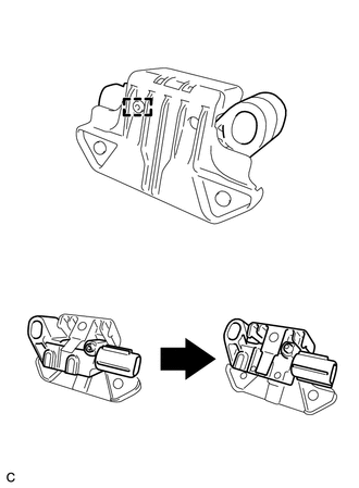
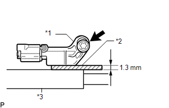
(a) Install the seat position sensor to the seat slide position sensor protector with the pin as shown in the illustration. |
|
|
(b) Using a 1.3 mm (0.0512 in.) feeler gauge, temporarily install the seat position sensor. Text in Illustration
NOTICE:
HINT: Be sure that the clearance between the seat position sensor and the seat rail is within 0.6 mm (0.0236 in.) to 2.0 mm (0.0787 in.). |
|
|
(c) Using a T30 "TORX" socket wrench, tighten the "TORX" screw to install the seat position sensor. Torque: 8.0 N·m {82 kgf·cm, 71 in·lbf} |
|
.png)
(d) Make sure that the clearance between the seat position sensor and the seat rail is within 0.6 mm (0.0236 in.) to 2.0 mm (0.0787 in.).
(e) Connect the connector.
(f) Check that there is no looseness in the installation parts of the seat position sensor.
2. INSTALL FRONT SEAT ASSEMBLY LH
(See page .gif) )
)
3. PERFORM DIAGNOSTIC SYSTEM CHECK
(a) Perform a diagnostic system check (See page
).
4. INSPECT SRS WARNING LIGHT
(a) Inspect the SRS warning light (See page
).
 Removal
REMOVAL
CAUTION / NOTICE / HINT
HINT:
Use the same procedure for the RH side and LH side.
The procedure listed below is for the LH side.
PROCEDURE
1. PRECAUTION
CAUTION:
Be su ...

Other materials about Toyota Venza:
Reassembly
REASSEMBLY
PROCEDURE
1. PRECAUTION
NOTICE:
After turning the ignition switch off, waiting time may be required before disconnecting
the cable from the negative (-) battery terminal. Therefore, make sure to read the
disconnecting the cable from the nega ...
How To Proceed With Troubleshooting
CAUTION / NOTICE / HINT
HINT:
Use the following procedure to troubleshoot the lighting system.
*: Use the Techstream.
PROCEDURE
1.
VEHICLE BROUGHT TO WORKSHOP
NEXT
...
System Description
SYSTEM DESCRIPTION
1. PUSH-BUTTON START DESCRIPTION
(a) The push-button start uses a push-type engine switch, which the driver can
operate by merely carrying the electrical key. This system consists primarily of
the power management control ECU, engine s ...

0.1436