Toyota Venza: Removal
REMOVAL
CAUTION / NOTICE / HINT
HINT:
- Use the same procedure for the RH side and LH side.
- The procedure listed below is for the LH side.
PROCEDURE
1. PRECAUTION
CAUTION:
Be sure to read Precaution thoroughly before servicing (See page
.gif) ).
).
2. DISCONNECT CABLE FROM NEGATIVE BATTERY TERMINAL
CAUTION:
Wait at least 90 seconds after disconnecting the cable from the negative (-) battery terminal to disable the SRS system.
NOTICE:
When disconnecting the cable, some systems need to be initialized after the cable
is reconnected (See page ).
3. REMOVE TONNEAU COVER ASSEMBLY (w/ Tonneau Cover)
4. REMOVE DECK BOARD ASSEMBLY
5. REMOVE NO. 3 DECK BOARD SUB-ASSEMBLY
6. REMOVE DECK SIDE TRIM BOX LH
7. REMOVE NO. 2 DECK BOARD SUB-ASSEMBLY
8. REMOVE DECK SIDE TRIM BOX RH
9. REMOVE NO. 1 DECK BOARD
10. REMOVE REAR SEAT SUB FLOOR PANEL ASSEMBLY
11. REMOVE REAR FLOOR FINISH PLATE
12. REMOVE RECLINING REMOTE CONTROL BEZEL
13. REMOVE LUGGAGE HOLD BELT STRIKER ASSEMBLY
14. REMOVE REAR DOOR SCUFF PLATE
15. DISCONNECT REAR DOOR OPENING TRIM WEATHERSTRIP
16. DISCONNECT REAR SEAT OUTER BELT ASSEMBLY
17. REMOVE DECK TRIM SIDE PANEL ASSEMBLY
18. REMOVE REAR AIRBAG SENSOR
(a) Check that the ignition switch is off.
(b) Check that the cable is disconnected from the negative (-) battery terminal.
CAUTION:
Wait at least 90 seconds after disconnecting the cable from the negative (-) battery terminal to disable the SRS system.
(c) Disconnect the connector from the rear airbag sensor.
NOTICE:
When disconnecting the airbag connector, take care not to damage the airbag wire harness.
(1) Push and hold the white housing lock, and slide the yellow outer connector locking sleeve.
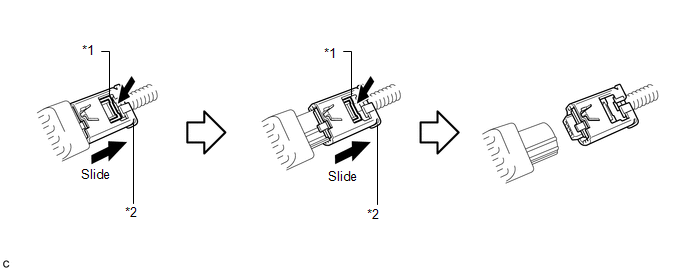 Text in Illustration
|
*1 |
Housing Lock |
*2 |
Outer Connector Locking Sleeve |
(2) Push and hold the white housing lock again, and slide the yellow outer connector locking sleeve to disconnect the connector.
|
(d) Remove the nut and rear airbag sensor. NOTICE: Loosen the nut while holding the rear airbag sensor because the rear airbag sensor pin (stopper) is easily damaged. |
|
.png)
 Installation
INSTALLATION
CAUTION / NOTICE / HINT
HINT:
Use the same procedure for the RH side and LH side.
The procedure listed below is for the LH side.
PROCEDURE
1. INSTALL REAR AIRBAG SE ...
 Seat Position Sensor
Components
COMPONENTS
ILLUSTRATION
On-vehicle Inspection
ON-VEHICLE INSPECTION
CAUTION / NOTICE / HINT
CAUTION:
Be sure to follow the correct removal and installation procedures of the se ...
Other materials about Toyota Venza:
Transfer Case Front Oil Seal(when Using The Engine Support Bridge)
Components
COMPONENTS
ILLUSTRATION
Replacement
REPLACEMENT
PROCEDURE
1. REMOVE TRANSFER ASSEMBLY
See page
2. REMOVE TRANSFER CASE FRONT OIL SEAL
(a) Using SST, remove the transfer case front oil seal from the transfer
case.
S ...
Installation
INSTALLATION
CAUTION / NOTICE / HINT
NOTICE:
When disconnecting the steering intermediate shaft assembly and pinion shaft
of the steering gear assembly, be sure to place matchmarks before servicing.
PROCEDURE
1. INSTALL TIE ROD ASSEMBLY LH
( ...
Power outlets
The power outlets can be used for 12V accessories that run on less than 10A.
►Console box
►Front passenger’s side instrument panel
►Luggage compartment
- The power outlets can be used when
►Vehicles with smart key sys ...

0.176