Toyota Venza: Seat Memory Switch
Components
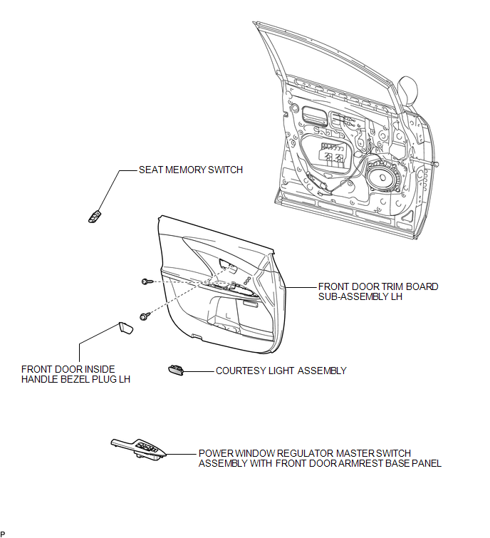
COMPONENTS
ILLUSTRATION
Removal
REMOVAL
PROCEDURE
1. REMOVE FRONT DOOR INSIDE HANDLE BEZEL PLUG LH
.gif)
2. REMOVE POWER WINDOW REGULATOR MASTER SWITCH ASSEMBLY WITH FRONT DOOR ARMREST BASE PANEL
3. REMOVE COURTESY LIGHT ASSEMBLY
4. REMOVE FRONT DOOR TRIM BOARD SUB-ASSEMBLY LH
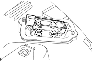
5. REMOVE SEAT MEMORY SWITCH
|
(a) Disengage the 4 claws and remove the seat memory switch from the front door trim board sub-assembly LH. |
|
Inspection
INSPECTION
PROCEDURE
1. INSPECT SEAT MEMORY SWITCH
|
(a) Measure the resistance according to the value(s) in the table below. Standard Resistance:
If the result is not as specified, replace the seat memory switch. |
|
.png)
Installation
INSTALLATION
PROCEDURE
1. INSTALL SEAT MEMORY SWITCH
(a) Engage the 4 claws to install the seat memory switch to the front door trim board sub-assembly LH.
2. INSTALL FRONT DOOR TRIM BOARD SUB-ASSEMBLY LH
.gif)
3. INSTALL COURTESY LIGHT ASSEMBLY
4. INSTALL POWER WINDOW REGULATOR MASTER SWITCH ASSEMBLY WITH FRONT DOOR ARMREST BASE PANEL
5. INSTALL FRONT DOOR INSIDE HANDLE BEZEL PLUG LH
 Seat Heater System
Precaution
PRECAUTION
1. NOTICE FOR INITIALIZATION
HINT:
When disconnecting the cable from the negative (-) battery terminal, initialize
the following systems after the cable is reconnected.
...
 Seat Belt
...
Other materials about Toyota Venza:
Catalyst System Efficiency Below Threshold (Bank 1) (P0420)
MONITOR DESCRIPTION
The ECM uses sensors mounted in front of and behind the Three-Way Catalytic Converter
(TWC) to monitor its efficiency.
The first sensor, the air fuel ratio sensor, sends pre-catalyst information to
the ECM. The second sensor, the heat ...
Lost Communication with ECM / PCM (U0100)
DESCRIPTION
DTC No.
DTC Detection Condition
Trouble Area
U0100
No communication from the ECM continues.
ECM main wire or connector
Power source circuit of ECM
ECM
...
Assist Map Number Un-Writing (C1581)
DESCRIPTION
The power steering ECU stores this DTC when it determines that the assist map
is not written in the ECU.
HINT:
The assist map is data written in the power steering ECU to control the degree
of assistance. The assist map is selected based on ...

0.1223