Toyota Venza: Door Mirror Foot Light
Components
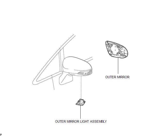
COMPONENTS
ILLUSTRATION
Removal
REMOVAL
CAUTION / NOTICE / HINT
HINT:
- Use the same procedure for both the RH and LH sides.
- The procedure described below is for the LH side.
PROCEDURE
1. REMOVE OUTER MIRROR
.gif)
2. REMOVE OUTER MIRROR LIGHT ASSEMBLY
|
(a) Disengage the 2 claws and guide from the outer rear view mirror assembly. |
|
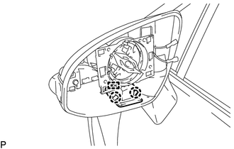
(b) Disconnect the connector and remove the outer mirror light assembly.
Inspection
INSPECTION
PROCEDURE
1. INSPECT OUTER MIRROR LIGHT ASSEMBLY LH
|
(a) Connect a positive (+) lead from the battery to terminal 1 and a negative (-) lead to terminal 2. |
|
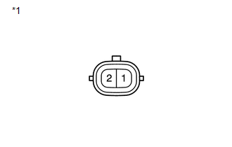
(b) Check that the outer mirror foot light comes on.
OK:
The light comes on.
Text in Illustration|
*1 |
Component without harness connected (Outer Mirror Light Assembly LH) |
If the result is not as specified, replace the outer mirror light assembly LH.
2. INSPECT OUTER MIRROR LIGHT ASSEMBLY RH
|
(a) Connect a positive (+) lead from the battery to terminal 1 and a negative (-) lead to terminal 2. |
|
(b) Check that the outer mirror foot light comes on.
OK:
The light comes on.
Text in Illustration|
*1 |
Component without harness connected (Outer Mirror Light Assembly RH) |
If the result is not as specified, replace the outer mirror light assembly RH.
Installation
INSTALLATION
CAUTION / NOTICE / HINT
HINT:
- Use the same procedure for both the RH and LH sides.
- The procedure described below is for the LH side.
PROCEDURE
1. INSTALL OUTER MIRROR LIGHT ASSEMBLY
(a) Connect the connector.
(b) Engage the guide and 2 claws to install the outer mirror light assembly.
2. INSTALL OUTER MIRROR
.gif)
 Automatic Light Control Sensor
Components
COMPONENTS
ILLUSTRATION
Removal
REMOVAL
PROCEDURE
1. REMOVE DEFROSTER NOZZLE GARNISH
2. REMOVE AUTOMATIC LIGHT CONTROL SENSOR
(a) Disengage the 2 claws and remov ...
 Fog Light Assembly
Components
COMPONENTS
ILLUSTRATION
Disassembly
DISASSEMBLY
PROCEDURE
1. REMOVE FOG LIGHT BULB
(a) Turn the fog light bulb in the direction indicated by the arrow shown
in t ...
Other materials about Toyota Venza:
System Diagram
SYSTEM DIAGRAM
1. AUTOMATIC LIGHT CONTROL SYSTEM
2. LIGHT AUTO TURN-OFF SYSTEM
Communication Table
Transmitter
Receiver
Line
Data Name
Certification ECU (Smart Key ECU Assembly)
Mai ...
Power Back Door Touch Sensor
Components
COMPONENTS
ILLUSTRATION
Removal
REMOVAL
PROCEDURE
1. REMOVE UPPER BACK WINDOW PANEL TRIM
2. REMOVE BACK DOOR PANEL TRIM ASSEMBLY
3. DISCONNECT POWER BACK DOOR ROD (for LH Side)
4. REMOVE BACK DOOR TRIM COVER
5. REMOVE POW ...
Adjustment
ADJUSTMENT
CAUTION / NOTICE / HINT
HINT:
Centering bolts are used to mount the hood hinge and hood lock. The
hood and hood lock cannot be adjusted with the centering bolts installed.
Substitute the centering bolts with standard bolts when ...

0.1311