Toyota Venza: Power Window Master Switch
Components
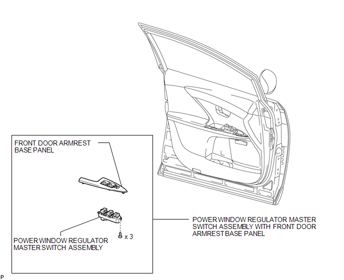
COMPONENTS
ILLUSTRATION
Removal
REMOVAL
PROCEDURE
1. REMOVE POWER WINDOW REGULATOR MASTER SWITCH ASSEMBLY WITH FRONT DOOR ARMREST BASE PANEL
.gif)
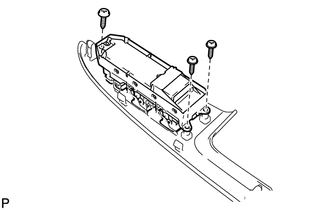
2. REMOVE POWER WINDOW REGULATOR MASTER SWITCH ASSEMBLY
|
(a) Remove the 3 screws and the power window regulator master switch assembly. |
|
Inspection
INSPECTION
PROCEDURE
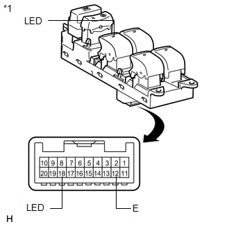
1. INSPECT POWER WINDOW REGULATOR MASTER SWITCH ASSEMBLY
|
(a) Check that the LED illuminates. (1) Apply battery voltage to the power window regulator master switch assembly and check that the LED illuminates. OK:
If the result is not as specified, replace the power window regulator master switch assembly. |
|
Installation
INSTALLATION
PROCEDURE
1. INSTALL POWER WINDOW REGULATOR MASTER SWITCH ASSEMBLY
|
(a) Install the power window regulator master switch assembly with the 3 screws. |
|
.png)
2. INSTALL POWER WINDOW REGULATOR MASTER SWITCH ASSEMBLY WITH FRONT DOOR ARMREST BASE PANEL
.gif)
 Jam Protection Function does not Operate
DESCRIPTION
This symptom may occur for any of the windows.
The jam protection function operates within a specified range during the manual
up or auto up operation.
CAUTION / NOTICE / HINT
NOT ...

Other materials about Toyota Venza:
Inspection
INSPECTION
PROCEDURE
1. INSPECT FRONT SEATBACK HEATER LH
(a) Apply battery voltage and check the seatback heater.
OK:
Measurement Connection
Condition
Specified Condition
...
Installation
INSTALLATION
PROCEDURE
1. INSTALL ROOF DRIP SIDE FINISH MOULDING CLIP (w/o Sliding Roof)
NOTICE:
If reusing the clips, do not remove the double-sided tape remaining
on the clips and where the clips will be installed on the body.
If installi ...
Brake
General Maintenance
GENERAL MAINTENANCE
PROCEDURE
1. INSPECT BRAKE LINE PIPES AND HOSES
HINT:
Work in a well-lighted area. Turn the front wheels fully to the right or left
before beginning the inspection.
(a) Using a mirror, check the entire circum ...

0.1448