Toyota Venza: Installation
INSTALLATION
PROCEDURE
1. INSTALL REAR SEAT ASSEMBLY RH
(a) Place the rear seat assembly RH in the cabin.
NOTICE:
Be careful not to damage the vehicle body.
|
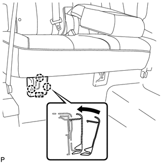
(b) Temporarily install the 2 bolts on the front side of the seat. |
|
.png)
|
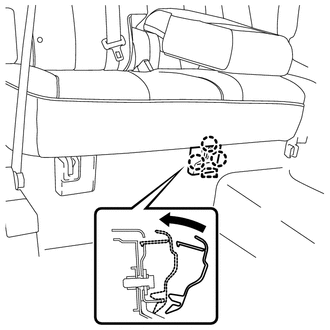
(c) Temporarily install the 3 bolts on the rear side of the seat. |
|
.png)
(d) Install the rear seat assembly RH with the 5 bolts.
Torque:
37 N·m {377 kgf·cm, 27 ft·lbf}
2. CONNECT REAR SEAT RECLINING CONTROL CABLE SUB-ASSEMBLY
(a) Connect the rear seat reclining control cable as shown in the illustration.
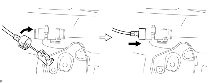
(b) Connect the rear seat reclining control cable sub-assembly as shown in the illustration.
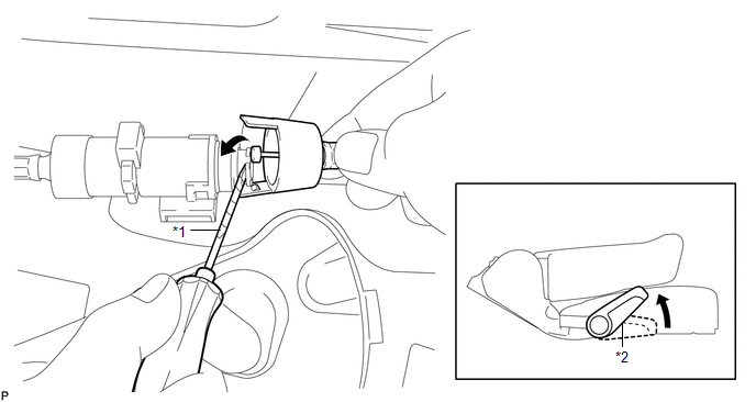 Text in Illustration
|
*1 |
Protective Tape |
*2 |
Seat Track Adjusting Handle |
|
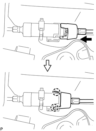
(c) Engage the 2 claws and connect the rear seat reclining control cable sub-assembly as shown in the illustration. |
|
(d) Return the seatback to the upright position.
(e) Pull up the adjuster's lock piece to lock it as shown in the illustration.
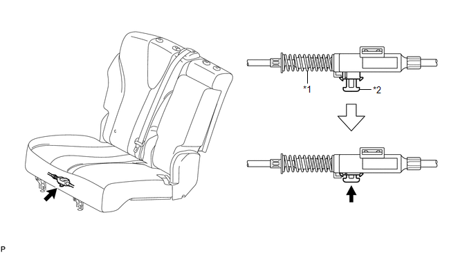 Text in Illustration
|
*1 |
Adjuster Spring |
*2 |
Lock Piece |
NOTICE:
When pressing the lock piece, make sure the adjuster's spring is not compressed.
3. INSTALL REAR SEAT OUTER TRACK BRACKET COVER
|
(a) Engage the 3 claws and guide, and install the rear seat outer track bracket cover as shown in the illustration. |
|
4. INSTALL REAR SEAT INNER TRACK BRACKET COVER
|
(a) Engage the 3 claws and guide, and install the rear seat inner track bracket cover as shown in the illustration. |
|
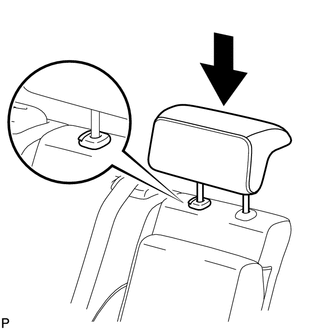
5. INSTALL REAR SEAT CENTER HEADREST ASSEMBLY
|
(a) Install the rear seat center headrest assembly as shown in the illustration. |
|
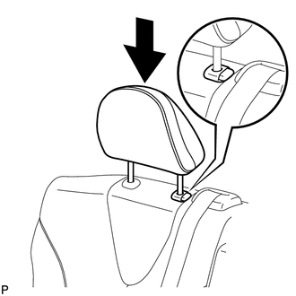
6. INSTALL REAR SEAT HEADREST ASSEMBLY
|
(a) Install the rear seat headrest assembly as shown in the illustration. |
|
 Reassembly
REASSEMBLY
PROCEDURE
1. INSTALL REAR SEAT LEG ASSEMBLY RH
(a) Using a T55 "TORX" socket wrench, install the rear seat leg assembly
RH with the 5 "TORX" bolts.
...
 Seat Heater Control
Components
COMPONENTS
ILLUSTRATION
Installation
INSTALLATION
PROCEDURE
1. INSTALL SEAT HEATER CONTROL SUB-ASSEMBLY
(a) Engage the clamp and install the seat heater control sub- ...
Other materials about Toyota Venza:
Diagnostic Trouble Code Chart
DIAGNOSTIC TROUBLE CODE CHART
HINT:
Parameters listed in the chart may not be exactly the same as your readings due
to the type of instrument or other factors. If a trouble code is displayed during
the DTC check, inspect the trouble areas listed for that ...
Installation
INSTALLATION
PROCEDURE
1. INSTALL SEPARATE TYPE FRONT SEAT CUSHION COVER
(a) Using a tacker, install the separate type front seat cushion heater
to the end of the separate type front seat cushion cover with 25 new tack
pins.
NOTICE:
...
Check For Intermittent Problems
CHECK FOR INTERMITTENT PROBLEMS
HINT:
Inspect the ECM using check mode. Intermittent problems are easier to detect
with the Techstream when the ECM is in check mode. In check mode, the ECM uses 1
trip detection logic, which is more sensitive to malfuncti ...

0.1388