Toyota Venza: Installation
INSTALLATION
PROCEDURE
1. INSTALL AIR CONDITIONING UNIT ASSEMBLY
(a) Install the air conditioning unit assembly with the 3 nuts.
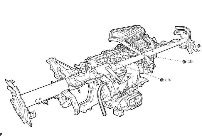
Torque:
9.8 N·m {100 kgf·cm, 87 in·lbf}
NOTICE:
Tighten the nuts in the order shown in the illustration to install the air conditioning unit assembly.
2. INSTALL INSTRUMENT PANEL REINFORCEMENT ASSEMBLY WITH AIR CONDITIONING UNIT ASSEMBLY
(a) Driver Side:
(1) Using a T40 "TORX" socket wrench, install the 2 "TORX" bolts.
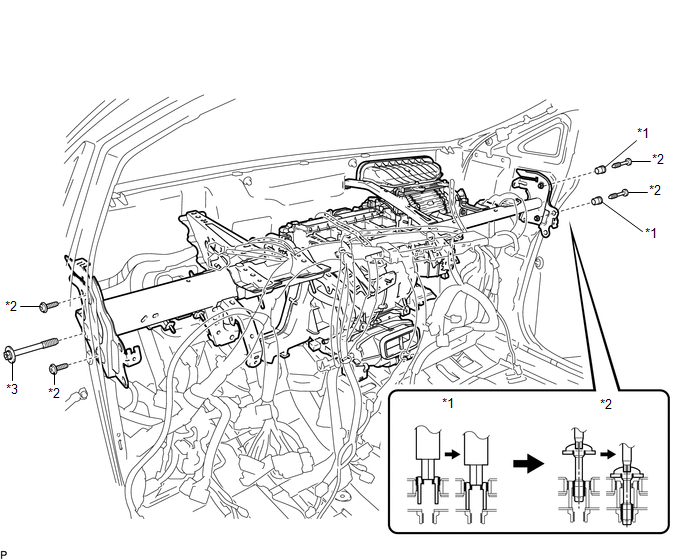 Text in Illustration
|
*1 |
Collar |
*2 |
"TORX" Bolt |
|
*3 |
Bolt |
- |
- |
Torque:
19 N·m {194 kgf·cm, 14 ft·lbf}
(2) Install the bolt.
Torque:
19 N·m {194 kgf·cm, 14 ft·lbf}
(b) Passenger Side:
(1) Using a 12 mm hexagon wrench, install the 2 collars for adjustment.
Torque:
6.0 N·m {61 kgf·cm, 53 in·lbf}
(2) Using a T40 "TORX" socket wrench, install the 2 "TORX" bolts.
Torque:
19 N·m {194 kgf·cm, 14 ft·lbf}
(c) for LH side:
(1) Install the hole plug.
(d) for RH side:
(1) Install the hole plug.
(e) Install the 2 bolts to the engine compartment side.
Torque:
17 N·m {173 kgf·cm, 13 ft·lbf}
(f) Install the instrument panel reinforcement assembly with air conditioning unit assembly with the nut.
Torque:
9.8 N·m {100 kgf·cm, 87 in·lbf}
(g) Connect the cooler drain hose.
(h) Install the bolt.
Torque:
19 N·m {194 kgf·cm, 14 ft·lbf}
(i) Install the 2 nuts and screw.
(j) Engage each clamp.
(k) Connect the blower motor connector.
(l) Connect each connector.
3. INSTALL NO. 2 INSTRUMENT PANEL BRACE SUB-ASSEMBLY
(a) Install the screw.
(b) Install the No. 2 instrument panel brace sub-assembly with the bolt and 2 nuts.
(c) Connect the earth wire with the bolt.
Torque:
8.4 N·m {86 kgf·cm, 74 in·lbf}
(d) Engage each clamp.
4. INSTALL NO. 1 INSTRUMENT PANEL BRACE SUB-ASSEMBLY
(a) Install the screw.
(b) Install the No. 1 instrument panel brace sub-assembly with the 2 bolts and 2 nuts.
(c) Connect the earth wire with the bolt.
Torque:
8.4 N·m {86 kgf·cm, 74 in·lbf}
(d) Engage each clamp.
5. INSTALL NO. 3 INSTRUMENT PANEL REINFORCEMENT
(a) Install the No. 3 instrument panel reinforcement with the 2 nuts.
(b) Connect the earth wire with the bolt.
Torque:
8.4 N·m {86 kgf·cm, 74 in·lbf}
(c) Engage the clamp.
6. INSTALL NO. 6 HEATER TO REGISTER DUCT ASSEMBLY
(a) Engage the 4 claws to install the No. 6 heater to register duct assembly.
(b) Engage the clamp.
7. INSTALL NO. 1 CONSOLE BOX DUCT
|
(a) Install the No. 1 console box duct with the clip as shown in the illustration. |
|
8. INSTALL FLOOR CARPET BRACKET LH
(a) Install the floor carpet bracket LH with the 3 clips.
(b) Engage the 2 clamps.
9. INSTALL REAR NO. 1 AIR DUCT
(a) Engage the 2 claws to install the rear No. 1 air duct.
10. INSTALL REAR NO. 2 AIR DUCT
|
(a) Engage the 4 claws to install the rear No. 2 air duct as shown in the illustration. |
|
11. INSTALL FLOOR CARPET BRACKET RH
(a) Install the floor carpet bracket RH with the 3 clips.
12. INSTALL REAR NO. 3 AIR DUCT
(a) Engage the 2 claws to install the rear No. 3 air duct.
13. INSTALL REAR NO. 4 AIR DUCT
|
(a) Engage the 4 claws to install the rear No. 4 air duct as shown in the illustration. |
|
14. INSTALL POWER STEERING ECU ASSEMBLY
.gif)
15. INSTALL MAIN BODY ECU (DRIVER SIDE JUNCTION BLOCK ASSEMBLY)
16. INSTALL TIRE PRESSURE WARNING ECU
17. INSTALL 4WD CONTROL ECU (for AWD)
18. INSTALL POWER MANAGEMENT CONTROL ECU
19. INSTALL TURN SIGNAL FLASHER ASSEMBLY
20. INSTALL STEERING POST ASSEMBLY
(See page )
21. INSTALL INSTRUMENT PANEL SAFETY PAD ASSEMBLY
(See page )
22. INSTALL FRONT SEAT ASSEMBLY LH
(See page )
23. INSTALL FRONT SEAT ASSEMBLY RH
(See page )
24. CONNECT AIR CONDITIONING TUBE AND ACCESSORY ASSEMBLY
(a) Remove the attached vinyl tape from the pipe.
(b) Sufficiently apply compressor oil to a new O-ring and fitting surface of the air conditioning tube and accessory assembly.
Compressor oil:
ND-OIL 8 or equivalent
(c) Install the O-ring on the air conditioning tube and accessory assembly.
NOTICE:
Keep the O-ring and O-ring fitting surfaces free from dirt or any foreign objects.
(d) Install the air conditioning tube and accessory assembly.
25. CONNECT SUCTION HOSE SUB-ASSEMBLY
(a) Remove the attached vinyl tape from the pipe.
(b) Sufficiently apply compressor oil to a new O-ring and the fitting surface of the suction hose sub-assembly.
Compressor oil:
ND-OIL 8 or equivalent
(c) Install the O-ring on the suction hose sub-assembly.
NOTICE:
Keep the O-ring and O-ring fitting surfaces free from dirt or any foreign objects.
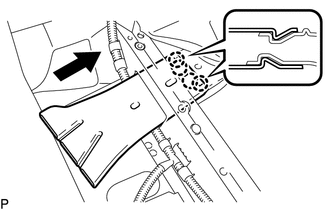
(d) Install the suction hose sub-assembly.
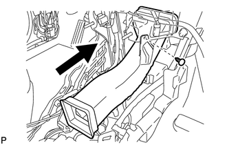
|
(e) Move the hook connector in the direction indicated by the arrow in the illustration. |
|
(f) Insert the pipe joint into the fitting hole securely and tighten the bolt.
Torque:
9.8 N·m {100 kgf·cm, 87 in·lbf}
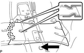
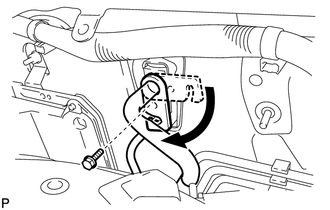
26. CONNECT INLET HEATER WATER HOSE
(a) Using pliers, grip the claws of the clip and slide the clip to connect the inlet heater water hose.
27. CONNECT OUTLET HEATER WATER HOSE
(a) Using pliers, grip the claws of the clip and slide the clip to connect the outlet heater water hose.
28. INSTALL OUTER COWL TOP PANEL
29. INSTALL WINDSHIELD WIPER MOTOR AND LINK ASSEMBLY
(See page )
30. ADD ENGINE COOLANT (for 1AR-FE)
31. ADD ENGINE COOLANT (for 2GR-FE)
32. INSPECT FOR COOLANT LEAK (for 1AR-FE)
33. INSPECT FOR COOLANT LEAK (for 2GR-FE)
34. CHARGE WITH REFRIGERANT
35. WARM UP ENGINE
36. INSPECT FOR REFRIGERANT LEAK
37. INITIALIZATION SERVO MOTOR
(a) Turn the ignition switch off.
(b) Connect the Techstream to the DLC3.
(c) Turn the ignition switch to on.
(d) Press the A/C OFF switch.
(e) Turn the Techstream on.
(f) Enter the following menus: Body Electrical / Air Conditioner / Utility / Servomotor Initialization.
(g) According to the Techstream display, select the "Next" switch.
(h) According to the Techstream display, select the "Next" switch.
HINT:
During initialization, the AUTO indicator illuminates. When initialization is complete, the indicator turns off.
(i) According to the Techstream display, select the exit to finish the initialization.
 Reassembly
REASSEMBLY
PROCEDURE
1. INSTALL AIR OUTLET CONTROL SERVO MOTOR SUB-ASSEMBLY
(a) Check that the slots, links and gears of the air outlet control servo
motor sub-assembly are positione ...
 Ambient Temperature Sensor
Components
COMPONENTS
ILLUSTRATION
Inspection
INSPECTION
PROCEDURE
1. INSPECT AMBIENT TEMPERATURE SENSOR
(a) Measure the resistance according to the value(s) in the table below.
Stan ...
Other materials about Toyota Venza:
Installation
INSTALLATION
PROCEDURE
1. INSTALL REAR DOOR BELT MOULDING
(a) Engage the 5 claws to install the rear door belt moulding.
2. INSTALL REAR DOOR GLASS SUB-ASSEMBLY
3. INSTALL REAR DOOR WINDOW DIVIS ...
Main Body ECU Vehicle Information Reading/Writing Process Malfunction (B15F6)
DESCRIPTION
This DTC is stored when items controlled by the main body ECU (multiplex network
body ECU) cannot be customized via the navigation system vehicle customization screen.
HINT:
The main body ECU (multiplex network body ECU) controls the items ...
Voice is not Recognized
PROCEDURE
1.
CHECK CONDITION
(a) Check if the system voice recognition level is low when recognizing a particular
voice.
Result
Proceed to
System voice recognition level is low with an ...

0.1455