Toyota Venza: Room Light
Components
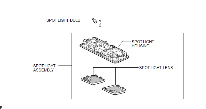
COMPONENTS
ILLUSTRATION
Removal
REMOVAL
PROCEDURE
1. REMOVE SPOT LIGHT ASSEMBLY
|
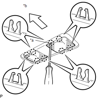
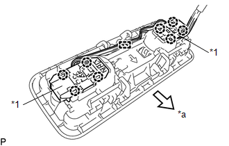
(a) Using a screwdriver with its tip wrapped with protective tape, disengage the 8 claws to remove the 2 spot light lenses. Text in Illustration
|
|
|
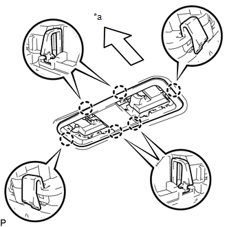
(b) Using a screwdriver with its tip wrapped with protective tape and moulding remover, disengage the 2 claws (A). Text in Illustration
|
|
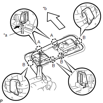
(c) Disengage the 4 claws (B) and disconnect the spot light housing.
|
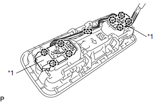
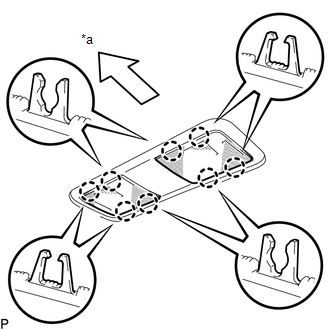
(d) Using a screwdriver, disengage the 8 claws and clamp to remove the spot light housing from the 2 map light sub-assemblies. Text in Illustration
|
|
2. REMOVE SPOT LIGHT BULB
(a) Remove the 2 spot light bulbs from the 2 map light sub-assemblies.
Installation
INSTALLATION
PROCEDURE
1. INSTALL SPOT LIGHT BULB
(a) Install the 2 spot light bulbs to the 2 map light sub-assemblies.
2. INSTALL SPOT LIGHT ASSEMBLY
|
(a) Engage the 8 claws and clamp to connect the spot light housing to the 2 map light sub-assemblies as shown in the illustration. Text in Illustration
|
|
|
(b) Engage the 6 claws to install the spot light housing. Text in Illustration
|
|
|
(c) Engage the 8 claws to install the 2 spot light lenses. Text in Illustration
|
|
 Relay
Relay
On-vehicle Inspection
ON-VEHICLE INSPECTION
PROCEDURE
1. INSPECT DOME CUT RELAY
(a) Measure the resistance according to the value(s) in the table below.
Standard Resistance:
...
 Vanity Light
Components
COMPONENTS
ILLUSTRATION
Installation
INSTALLATION
PROCEDURE
1. INSTALL VANITY LIGHT ASSEMBLY
(a) Engage the 3 claws and install the vanity light assembly.
...
Other materials about Toyota Venza:
Power windows
The power windows can be opened and closed using the following switches.
1. One-touch closing*
2. Closing
3. One-touch opening*
4. Opening
*:To stop the window partway, operate the switch in the opposite direction.
Lock switch
Press the switch down ...
Intake Air Temperature Sensor Gradient Too High (P0111)
DESCRIPTION
The intake air temperature sensor, mounted on the mass air flow meter,
monitors the intake air temperature. The intake air temperature sensor has
a built-in thermistor with a resistance that varies according to the temperature
...
Disassembly
DISASSEMBLY
PROCEDURE
1. REMOVE MAGNETIC SWITCH ASSEMBLY
(a) Remove the nut and disconnect the lead wire from the magnetic switch.
(b) Remove the 2 screws holding the magnetic switch to t ...

0.1764