Toyota Venza: Inspection
INSPECTION
PROCEDURE
1. INSPECT SPIRAL CABLE
(a) Visually check for defects with the spiral cable removed from the vehicle.
(1) The defects are as follows:
- Scratches on the spiral cable
- Small cracks the spiral cable
- Dents on the spiral cable
- Chips on the spiral cable
- Cracks or other damage to the connector
OK:
No defects are found.
HINT:
If any of the defects is found, replace the spiral cable with a new one.
|
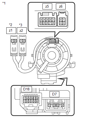
(b) Inspect the spiral cable. Text in Illustration
(1) Measure the resistance according to the value(s) in the table below. NOTICE: To avoid breakage of the spiral cable, do not turn the spiral cable more than necessary. If the value is not within the specified range, replace the spiral cable. Standard Resistance
|
|
 Components
COMPONENTS
ILLUSTRATION
...
 Removal
REMOVAL
PROCEDURE
1. PRECAUTION
CAUTION:
Be sure to read Precaution thoroughly before servicing (See page
).
2. TURN FRONT WHEELS TO FACE STRAIGHT AHEAD
3. DISCONNECT CABLE FROM NEGATIVE BATTE ...
Other materials about Toyota Venza:
EVAP System
RELATED DTCS
DTC No.
Monitoring Item
See page
P043E
Reference orifice clogged (built into canister pump module)
P043F
Reference orifice high-flow (built into ...
Emission Control System
Parts Location
PARTS LOCATION
ILLUSTRATION
On-vehicle Inspection
ON-VEHICLE INSPECTION
PROCEDURE
1. INSPECT FUEL CUT-OFF RPM
(a) Increase the engine speed to at least 3500 rpm.
(b) Use a sound scope to check for injector operating soun ...
Problem Symptoms Table
PROBLEM SYMPTOMS TABLE
HINT:
Use the table below to help determine the cause of problem symptoms. If multiple
suspected areas are listed, the potential causes of the symptoms are listed in order
of probability in the "Suspected Area" column of ...

0.1159