Toyota Venza: Removal
REMOVAL
CAUTION / NOTICE / HINT
NOTICE:
If automatic transaxle assembly parts are replaced, refer to Parts Replacement
Compensation Table to determine if any additional operations are necessary (See
page .gif) ).
).
PROCEDURE
1. DISCHARGE FUEL PRESSURE
See page
2. ALIGN FRONT WHEELS FACING STRAIGHT AHEAD
3. SECURE STEERING WHEEL
4. DISCONNECT CABLE FROM NEGATIVE BATTERY TERMINAL
NOTICE:
When disconnecting the cable, some systems need to be initialized after the cable
is reconnected (See page ).
5. REMOVE FRONT WHEELS
6. REMOVE NO. 1 ENGINE UNDER COVER
7. REMOVE NO. 2 ENGINE UNDER COVER
8. REMOVE FRONT FENDER APRON RH
9. REMOVE FRONT FENDER APRON LH
10. DRAIN ENGINE COOLANT
11. DRAIN AUTOMATIC TRANSAXLE FLUID
12. REMOVE COOL AIR INTAKE DUCT SEAL
13. REMOVE V-BANK COVER SUB-ASSEMBLY
14. REMOVE INLET NO. 2 AIR CLEANER
15. REMOVE AIR CLEANER CAP WITH HOSE
16. REMOVE AIR CLEANER CASE
17. REMOVE BATTERY
18. REMOVE INLET NO. 1 AIR CLEANER
19. REMOVE INTAKE AIR SURGE TANK ASSEMBLY
See page
20. REMOVE ECM
21. DISCONNECT TRANSMISSION CONTROL CABLE ASSEMBLY
22. REMOVE TCM
23. REMOVE STARTER ASSEMBLY
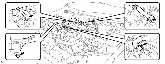
24. DISCONNECT WIRE HARNESS
|
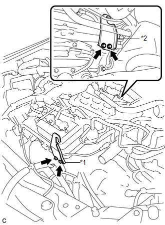
(a) Remove the 2 bolts and disconnect the 2 wire harnesses from the automatic transaxle assembly. |
|
.png)
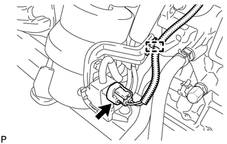
(b) Disconnect the park/neutral position switch assembly connector and 7 wire harness clamps from the automatic transaxle assembly.
|
(c) Disconnect the clamp and connector. |
|
25. REMOVE FLEXIBLE HOSE BRACKET SUB-ASSEMBLY
|
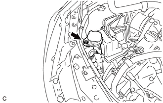
(a) Disconnect the No. 1 breather plug (ATM) from the flexible hose bracket sub-assembly. |
|
.png)
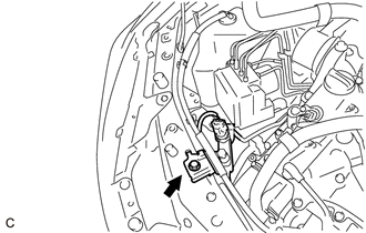
(b) Remove the bolt and flexible hose bracket sub-assembly from the camshaft housing sub-assembly LH.
26. REMOVE FRONT EXHAUST PIPE ASSEMBLY
See page
27. REMOVE MANIFOLD STAY
28. REMOVE FRONT DRIVE SHAFT ASSEMBLY
See page
29. REMOVE NO. 1 EXHAUST PIPE SUPPORT BRACKET
30. REMOVE FLYWHEEL HOUSING UNDER COVER
31. REMOVE DRIVE PLATE AND TORQUE CONVERTER ASSEMBLY SETTING BOLT
32. REMOVE FRONT FLOOR BRACE
33. DISCONNECT NO. 1 RADIATOR HOSE
34. INSTALL ENGINE HANGERS
|
(a) Install the No. 1 and No. 2 engine hangers with the 4 bolts. Text in Illustration
Torque: 33 N·m {337 kgf·cm, 24 ft·lbf} Part No.:
|
|
35. INSTALL ENGINE SUPPORT BRIDGE
|
(a) Remove the bolt and tank cap sub-assembly. |
|
|
(b) Remove the bolt and disconnect the air conditioner tube and accessory assembly. |
|
(c) Disengage the clamp and remove the nut and 3 bolts from the engine wire.
 Text in Illustration
|
*a |
Nut |
- |
- |
|
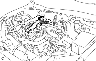
(d) Move the engine wire as shown in the illustration. NOTICE: Position the engine wire so that it will not interfere with the chains when the engine with automatic transaxle assembly is suspended. |
|
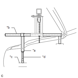
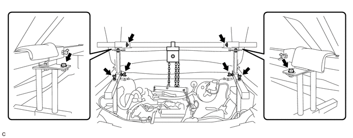
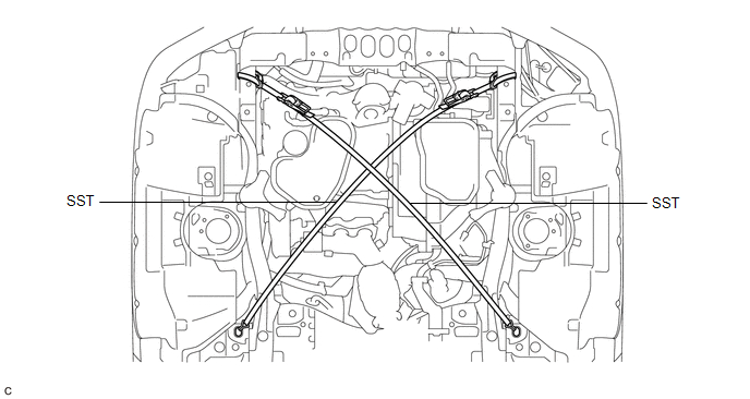
(e) Install SST to the vehicle body as shown in the illustration.
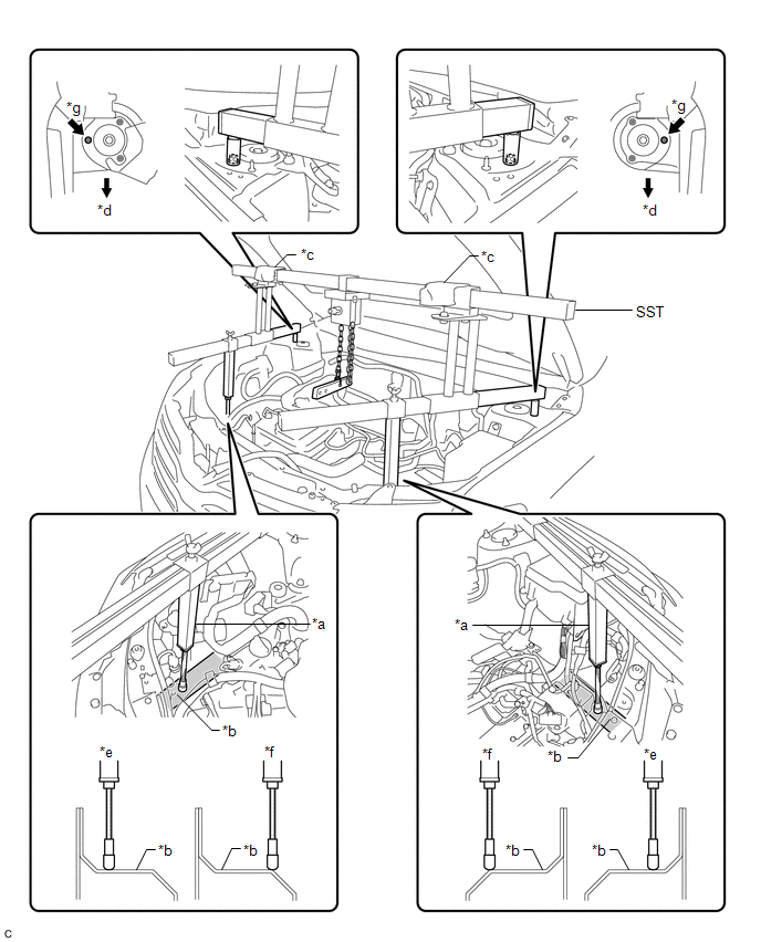 Text in Illustration
|
*a |
Support Shaft |
*b |
Side Member |
|
*c |
Cloth |
*d |
Front Side |
|
*e |
Correct |
*f |
Incorrect |
|
*g |
Front Suspension Nut |
- |
- |
SST: 09940-10020
CAUTION:
Make sure the fuse bolt is not deformed.
 Text in Illustration
|
*a |
Fuse Bolt |
|
*b |
Correct |
|
*c |
Incorrect |
NOTICE:
- Prevent SST from contacting the vehicle body or windshield.
- To prevent damage to the engine hood, place pieces of cloth between the engine hood and SST.
- Lightly shake SST by hand to make sure it is securely installed while performing work.
- Set the support shafts on level surfaces.
|
(f) Turn the threaded portion of each support shaft to adjust its height and make the SST sub beams parallel to the ground. Text in Illustration
|
|
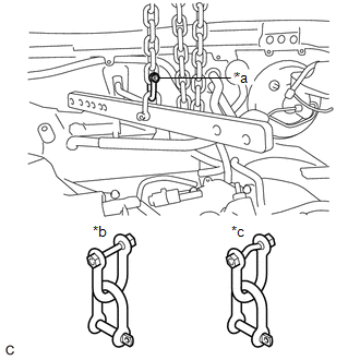
(g) Connect each chain to the division bar with the shackles at the position shown in the illustration.
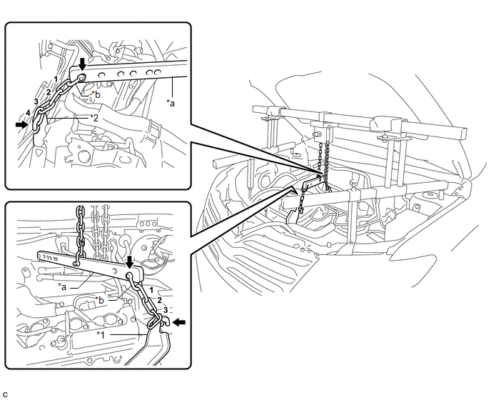 Text in Illustration
|
*1 |
No. 2 Engine Hanger |
*2 |
No. 1 Engine Hanger |
|
*a |
Division Bar |
*b |
Shackle |
(h) Connect the 4th link of the chain to the No. 1 engine hanger.
(i) Connect the 3rd link of the chain to the No. 2 engine hanger.
(j) Make sure the distance between the chain block assembly and division bar is 50 mm (1.97 in.) or more.
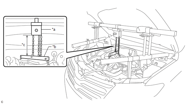 Text in Illustration
|
*a |
Chain Block Assembly |
*b |
Division Bar |
|
*c |
50 mm (1.97 in.) or more |
- |
- |
(k) Adjust the position of the chain block assembly so that the chain is perpendicular to the SST main beam and sub beams as shown in the illustration.
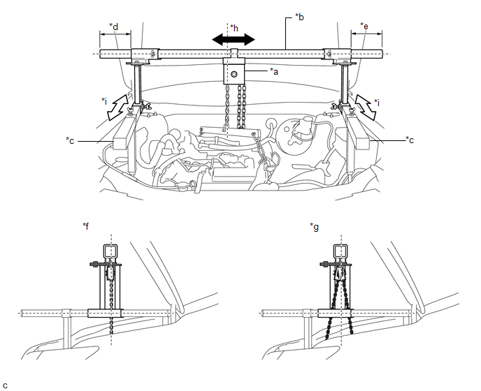 Text in Illustration
|
*a |
Chain Block Assembly |
*b |
Main Beam |
|
*c |
Sub Beam |
*d |
Dimension (A) |
|
*e |
Dimension (B) |
*f |
Correct |
|
*g |
Incorrect |
*h |
Right to Left Adjustment |
|
*i |
Front to Rear Adjustment |
- |
- |
CAUTION:
To prevent the engine with automatic transaxle assembly from falling, make sure that the dimension (A) and dimension (B) are equal.
(l) Tighten the 6 wing bolts and 2 bolts.
Torque:
for Bolt :
30 N·m {306 kgf·cm, 22 ft·lbf}
|
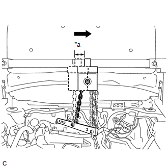
(m) Move the chain block assembly approximately 50 mm (1.97 in.) as shown in the illustration. Text in Illustration
|
|
|
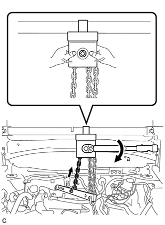
(n) Tighten the chain block assembly until it cannot be moved any further by hand. Text in Illustration
NOTICE:
|
|
36. INSTALL BELT
|
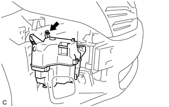
(a) Remove the 2 bolts. |
|
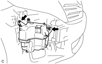
|
(b) Loosen the nut and disconnect the windshield washer jar assembly from the vehicle body. NOTICE: Do not remove the nut. |
|
(c) Install SST to the vehicle body as shown in the illustration.
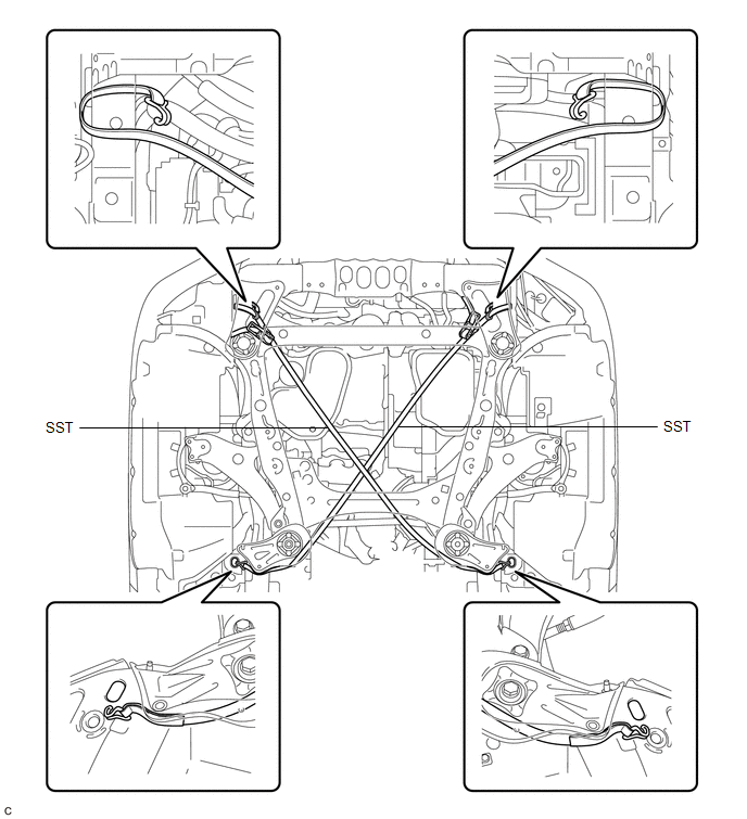
SST: 09727-00110
(d) Using the SST ratchet buckle, tighten the SST belt until there is no slack.
 Text in Illustration
|
*a |
Ratchet Buckle |
- |
- |
37. REMOVE FRONT FRAME ASSEMBLY
See page
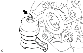
38. REMOVE ENGINE MOUNTING INSULATOR RH
|
(a) Remove the nut and engine mounting insulator RH from the engine mounting bracket RH. |
|
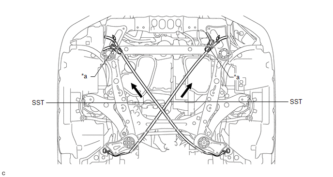
39. INSTALL SUPPORT BAR
(a) Install the SST (support bar) to the vehicle body with the 2 bolts as shown in the illustration.
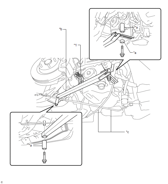 Text in Illustration
|
*1 |
Engine Mounting Bracket RH |
- |
- |
|
*a |
Spacer |
*b |
SST (Support Bar) |
|
*c |
SST (Belt) |
- |
- |
SST: 09944-10020
CAUTION:
To prevent the engine with automatic transaxle assembly from falling while servicing, do not remove SST (belt).
(b) Install the bolt to the engine mounting bracket RH.
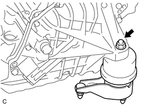
40. REMOVE FRONT ENGINE MOUNTING INSULATOR ASSEMBLY
|
(a) Remove the bolt and front engine mounting insulator assembly from the front engine mounting bracket. |
|
41. REMOVE ENGINE MOUNTING INSULATOR LH
|
(a) Remove the nut and engine mounting insulator LH from the automatic transaxle assembly. |
|
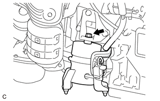
42. DISCONNECT OUTLET NO. 1 OIL COOLER HOSE
|
(a) Slide the clip and disconnect the outlet No. 1 oil cooler hose from the automatic transaxle assembly. |
|
.png)
43. DISCONNECT INLET NO. 1 OIL COOLER HOSE
|
(a) Slide the clip and disconnect the inlet No. 1 oil cooler hose from the automatic transaxle assembly. |
|
.png)
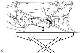
44. SUPPORT ENGINE ASSEMBLY
|
(a) Set an engine lifter. CAUTION: To prevent the engine with automatic transaxle assembly from falling while servicing, do not remove SST. NOTICE: Make sure that there is a clearance between the engine oil pan assembly and engine lifter. |
|
45. REMOVE BELT
(a) Remove SST from the vehicle body.
46. REMOVE AUTOMATIC TRANSAXLE ASSEMBLY
(a) Support the automatic transaxle assembly with a transmission jack.
NOTICE:
- In order to protect the automatic transaxle oil pan sub-assembly, place attachments on the transmission jack.
- Make sure that the attachments and automatic transaxle oil pan sub-assembly are centered on the transmission jack.
- To prevent the automatic transaxle oil pan sub-assembly from being deformed, do not place any attachments under the automatic transaxle oil pan sub-assembly.
|
(b) Remove the 11 bolts and automatic transaxle assembly from the engine assembly. NOTICE:
|
|
.png)
47. REMOVE TORQUE CONVERTER ASSEMBLY
(a) Remove the torque converter assembly from the automatic transaxle assembly.
48. REMOVE FRONT ENGINE MOUNTING BRACKET
|
(a) Remove the 3 bolts and front engine mounting bracket from the automatic transaxle assembly. |
|
.png)
49. REMOVE WIRE HARNESS CLAMP BRACKET
|
(a) Remove the 4 bolts and 4 wire harness clamp brackets from the automatic transaxle assembly. |
|
.png)
50. REMOVE NO. 1 TRANSMISSION CONTROL CABLE BRACKET
|
(a) Remove the 2 bolts and No. 1 transmission control cable bracket from the automatic transaxle assembly. |
|
.png)
51. REMOVE SPEEDOMETER DRIVEN HOLE (ATM) COVER SUB-ASSEMBLY
|
(a) Remove the bolt and speedometer driven hole (ATM) cover sub-assembly from the automatic transaxle assembly. |
|
.png)
(b) Remove the O-ring from the speedometer driven hole (ATM) cover sub-assembly.
 Components
COMPONENTS
ILLUSTRATION
ILLUSTRATION
ILLUSTRATION
ILLUSTRATION
ILLUSTRATION
...
 Installation
INSTALLATION
PROCEDURE
1. INSPECT TORQUE CONVERTER ASSEMBLY
2. INSTALL TORQUE CONVERTER ASSEMBLY
(a) Engage the splines of the input shaft and turbine runner.
...
Other materials about Toyota Venza:
Front Blower Motor
Components
COMPONENTS
ILLUSTRATION
Installation
INSTALLATION
PROCEDURE
1. INSTALL FRONT BLOWER MOTOR SUB-ASSEMBLY
(a) Install the front blower motor sub-assembly with the 3 screws.
(b) Con ...
Power windows
The power windows can be opened and closed using the following switches.
1. One-touch closing*
2. Closing
3. One-touch opening*
4. Opening
*:To stop the window partway, operate the switch in the opposite direction.
Lock switch
Press the switch down ...
Reassembly
REASSEMBLY
PROCEDURE
1. INSTALL FRONT SIDE MARKER LIGHT BULB
(a) Install the front side marker light bulb to the front side marker light socket.
(b) Turn the front side marker light socket with the front side marker
light bulb in the directi ...

0.1213