Toyota Venza: Components
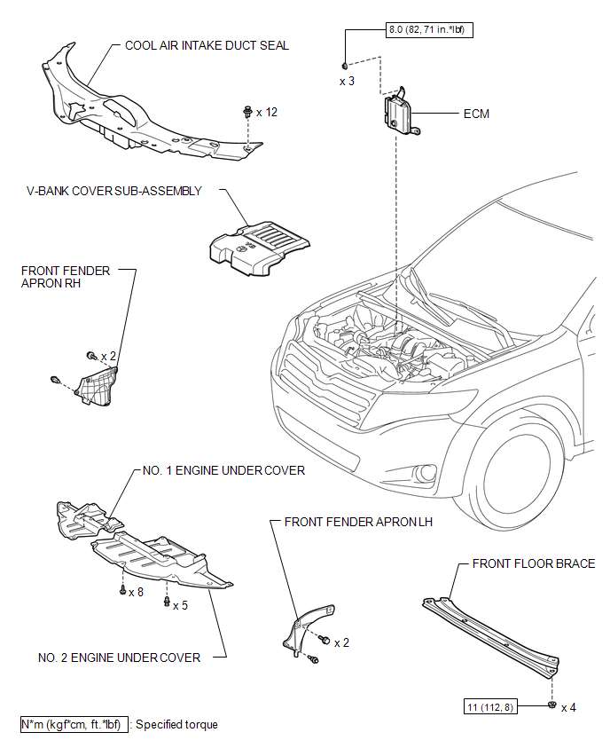
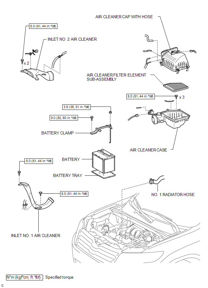
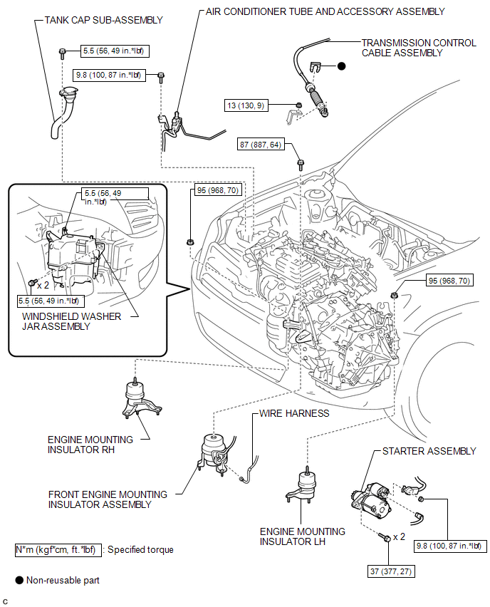
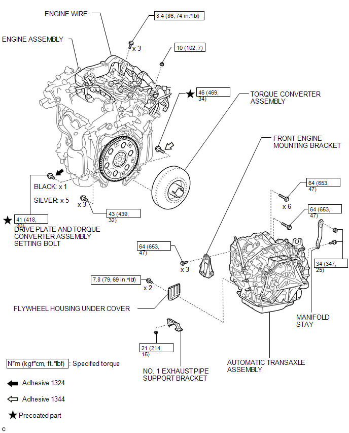
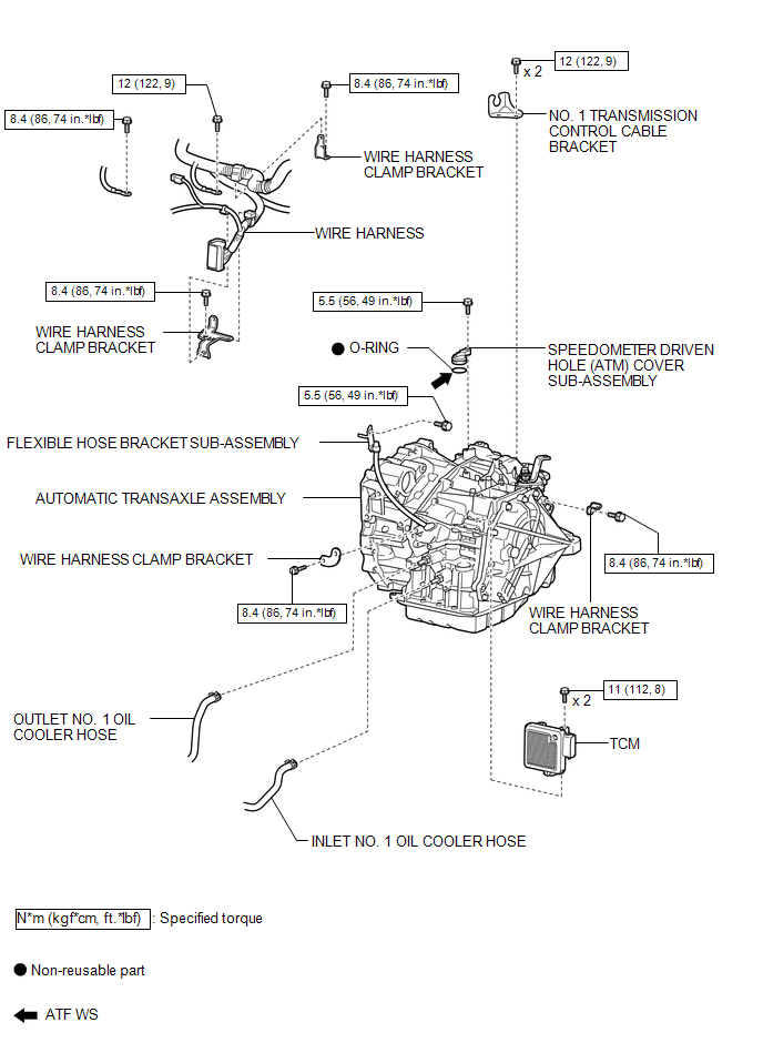
COMPONENTS
ILLUSTRATION
ILLUSTRATION
ILLUSTRATION
ILLUSTRATION
ILLUSTRATION

 Removal
REMOVAL
CAUTION / NOTICE / HINT
NOTICE:
If automatic transaxle assembly parts are replaced, refer to Parts Replacement
Compensation Table to determine if any additional operations are necessary ( ...
Other materials about Toyota Venza:
Tongue Plate Stopper
Components
COMPONENTS
ILLUSTRATION
Replacement
REPLACEMENT
PROCEDURE
1. REMOVE TONGUE PLATE STOPPER
(a) Slide the tongue plate above the installation position of the tongue
plate stopper, and temporarily hold it with adhesive tape.
...
Installing the spare tire
Remove any dirt or foreign matter from the wheel contact surface.
If foreign matter is on the wheel contact surface, the wheel nuts may loosen
while the vehicle is in motion, and the tire may come off the vehicle.
Install the spare tire and loosely tig ...
Disposal
DISPOSAL
PROCEDURE
1. DISPOSE OF REAR SHOCK ABSORBER
(a) Fully extend the shock absorber piston rod.
(b) Using a drill, make a hole in area B shown in the illustration to discharge
the gas inside. ...

0.1148