Toyota Venza: Front Blower Motor
Components
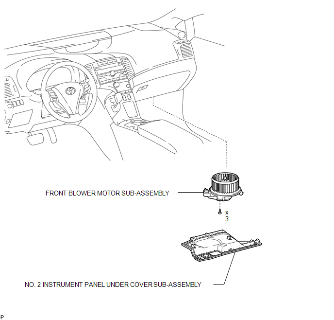
COMPONENTS
ILLUSTRATION
Installation
INSTALLATION
PROCEDURE
1. INSTALL FRONT BLOWER MOTOR SUB-ASSEMBLY
|
(a) Install the front blower motor sub-assembly with the 3 screws. |
|
(b) Connect the connector.
2. INSTALL NO. 2 INSTRUMENT PANEL UNDER COVER SUB-ASSEMBLY
.gif)
3. CONNECT CABLE TO NEGATIVE BATTERY TERMINAL
NOTICE:
When disconnecting the cable, some systems need to be initialized after the cable
is reconnected (See page ).
Removal
REMOVAL
PROCEDURE
1. DISCONNECT CABLE FROM NEGATIVE BATTERY TERMINAL
NOTICE:
When disconnecting the cable, some systems need to be initialized after the cable
is reconnected (See page .gif) ).
).
2. REMOVE NO. 2 INSTRUMENT PANEL UNDER COVER SUB-ASSEMBLY
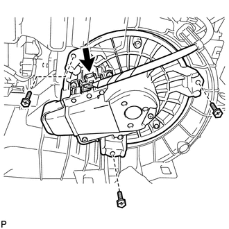
3. REMOVE FRONT BLOWER MOTOR SUB-ASSEMBLY
|
(a) Disconnect the connector. |
|
.png)
(b) Remove the 3 screws and front blower motor sub-assembly.
 Reassembly
REASSEMBLY
PROCEDURE
1. INSTALL COOLER DRYER
(a) Using pliers, install a new cooler dryer to the modulator.
(b) Apply sufficien ...

Other materials about Toyota Venza:
Installation
INSTALLATION
PROCEDURE
1. INSTALL ROOF DRIP SIDE FINISH MOULDING CLIP (w/o Sliding Roof)
NOTICE:
If reusing the clips, do not remove the double-sided tape remaining
on the clips and where the clips will be installed on the body.
If installi ...
Installation
INSTALLATION
PROCEDURE
1. TEMPORARILY INSTALL SLIDING ROOF HOUSING ASSEMBLY
(a) Temporarily install the sliding roof housing panel with the 18 nuts.
NOTICE:
When installing the housing to the vehicle, first install the housing
center front and ...
Mechanical System Tests
MECHANICAL SYSTEM TESTS
1. STALL SPEED TEST
HINT:
This test is to check the overall performance of the engine and transaxle.
CAUTION:
Driving test should be done on a paved surface (a surface that is not
slippery).
To ensure safety, perfor ...

0.1465