Toyota Venza: Reassembly
REASSEMBLY
PROCEDURE
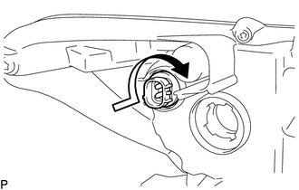
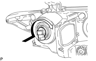
1. INSTALL FRONT SIDE MARKER LIGHT BULB
(a) Install the front side marker light bulb to the front side marker light socket.
|
(b) Turn the front side marker light socket with the front side marker light bulb in the direction indicated by the arrow shown in the illustration to install them as a unit. |
|
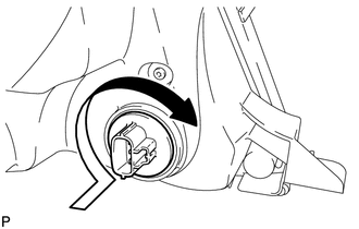
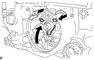
2. INSTALL FRONT TURN SIGNAL LIGHT BULB
(a) Install the front turn signal light bulb to the front turn signal light socket.
(b) for Halogen Headlight:
|
(1) Turn the front turn signal light socket with the front turn signal light bulb in the direction indicated by the arrow shown in the illustration to install them as a unit. |
|
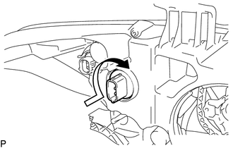
(c) for HID Headlight:
|
(1) Turn the front turn signal light socket with the front turn signal light bulb in the direction indicated by the arrow shown in the illustration to install them as a unit. |
|
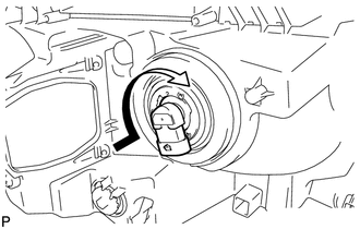
3. INSTALL NO. 1 HEADLIGHT BULB (for Halogen Headlight)
|
(a) Turn the No. 1 headlight bulb in the direction indicated by the arrow shown in the illustration to install it. NOTICE: Do not touch the bulb glass. |
|
4. INSTALL NO. 2 HEADLIGHT BULB (for Halogen Headlight)
|
(a) Turn the No. 2 headlight bulb in the direction indicated by the arrow shown in the illustration to install it. NOTICE: Do not touch the bulb glass. |
|
5. INSTALL DISCHARGE HEADLIGHT BULB (for HID Headlight)
(a) Set the discharge headlight bulb to the headlight unit.
NOTICE:
Do not touch the bulb glass.
|
(b) Lock the set spring to install the discharge headlight bulb as shown in the illustration. |
|
6. INSTALL LIGHT CONTROL ECU (for HID Headlight)
|
(a) Turn the socket of the light control ECU in the direction indicated by the arrow shown in the illustration to connect it. NOTICE:
|
|
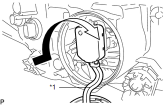
(b) Check that the red line on the output harness is not twisted and store the harness in the headlight assembly securely so that the output harness is not pinched.
Text in Illustration|
*1 |
Red Line |
|
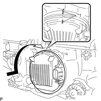
(c) Turn the light control ECU in the direction indicated by the arrow shown in the illustration until the lock marks are aligned to install it. Text in Illustration
NOTICE:
|
|
 Adjustment
ADJUSTMENT
CAUTION / NOTICE / HINT
HINT:
It is possible that a bulb is incorrectly installed, affecting headlight aim.
Bulb installation should be considered prior to performing the adjustment pr ...
 Installation
INSTALLATION
PROCEDURE
1. INSTALL HEADLIGHT ASSEMBLY
(a) Connect each connector.
(b) Install the headlight assembly with the bolt and 3 screws.
Torque:
3.6 N·m {37 kgf·cm, 32 in·lbf}
2. INS ...
Other materials about Toyota Venza:
System Diagram
SYSTEM DIAGRAM
Transmitting ECU
(Transmitter)
Receiving ECU
Signal
Communication Method
ECM
Power Steering ECU
Engine speed signal
Engine variation inform ...
Throttle / Pedal Position Sensor "A" Minimum Stop Performance (P2109)
DESCRIPTION
The idle speed is controlled by the Electronic Throttle Control System (ETCS).
The ETCS is comprised of a throttle actuator, which operates the throttle valve,
and a throttle position sensor, which detects the opening amount of the throttle
...
Electrical Key Oscillator(for Rear Floor)
Components
COMPONENTS
ILLUSTRATION
Removal
REMOVAL
PROCEDURE
1. REMOVE TONNEAU COVER ASSEMBLY (w/ Tonneau Cover)
2. REMOVE DECK BOARD ASSEMBLY
3. REMOVE NO. 3 DECK BOARD SUB-ASSEMBLY
4. REMOVE DECK SIDE TRIM BOX LH
5. REMOVE NO. 2 D ...

0.131