Toyota Venza: Removal
REMOVAL
PROCEDURE
1. REMOVE TAIL EXHAUST PIPE ASSEMBLY (for 1AR-FE)
.gif)
2. REMOVE TAIL EXHAUST PIPE ASSEMBLY (for 2GR-FE)
3. REMOVE CENTER EXHAUST PIPE ASSEMBLY (for 1AR-FE)
4. REMOVE CENTER EXHAUST PIPE ASSEMBLY (for 2GR-FE)
5. REMOVE PROPELLER WITH CENTER BEARING SHAFT ASSEMBLY
(a) Depress the brake pedal and hold it.
|
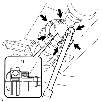
(b) Using a hexagon wrench (6 mm), loosen the cross groove joint set bolts 1/2 turn. NOTICE:
|
|
|
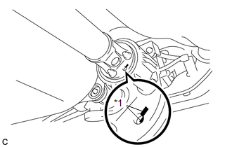
(c) Place matchmarks on the rear propeller shaft and electromagnetic control coupling assembly. Text in Illustration
|
|
|
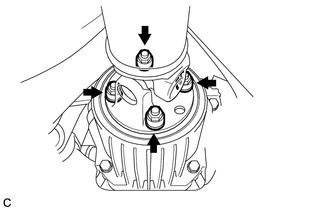
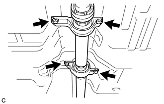
(d) Remove the 4 nuts and 4 washers. |
|
|
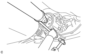
(e) Using a brass bar and a hammer, separate the propeller with center bearing shaft assembly. |
|
|
(f) Remove the 4 bolts, 2 No. 1 center support bearing washers and 2 No. 2 center support bearing washers. NOTICE: When removing the bolts and washers, do not apply excessive force to the universal joint. |
|
(g) Pull out the propeller with center bearing shaft assembly from the transfer.
NOTICE:
- When removing the propeller shaft, do not apply excessive force to the universal joint.
- During and after the removal of the propeller shaft, keep the universal joint angle straight (within 15 degrees).
- Be careful not to damage the oil seal.
|
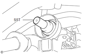
(h) Insert SST into the transfer to prevent oil leaks. SST: 09325-20010 NOTICE: Be careful not to damage the oil seal. |
|
 Components
COMPONENTS
ILLUSTRATION
ILLUSTRATION
ILLUSTRATION
ILLUSTRATION
...
 Disassembly
DISASSEMBLY
PROCEDURE
1. REMOVE PROPELLER SHAFT
(a) Place matchmarks on both flanges.
Text in Illustration
*1
Matchmark
...
Other materials about Toyota Venza:
Power Mirror Surface Position is not Memorized
SYSTEM DESCRIPTION
If either the M1 or M2 seat memory switch is pressed, the outer mirror control
ECU assembly (driver door) detects the switch operation and sends the seat memory
switch signal to the main body ECU (driver side junction block assembly) vi ...
Mass Air Flow Circuit Range / Performance Problem (P0101)
DESCRIPTION
Refer to DTC P0102 (See page ).
DTC No.
DTC Detection Condition
Trouble Area
P0101
All of the following conditions are met (2 trip detection logic):
(a) The engine is running.
(b ...
Front Axle Hub Bolt
Components
COMPONENTS
ILLUSTRATION
Replacement
REPLACEMENT
CAUTION / NOTICE / HINT
HINT:
Use the same procedure for the RH side and LH side.
The procedure listed below is for the LH side.
PROCEDURE
1. REMOVE FRONT WHEEL
2. SEP ...

0.1307