Toyota Venza: Torque Sensor Circuit Malfunction (C1511-C1514,C1517)
DESCRIPTION
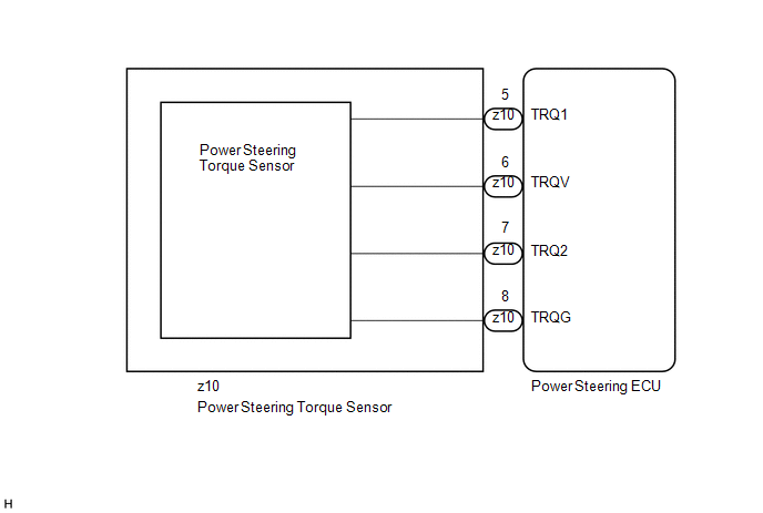
The torque sensor converts the rotation torque input to the steering wheel into an electrical signal and sends it to the power steering ECU. Based on this signal, the ECU detects steering effort.
|
DTC No. |
DTC Detection Condition |
Trouble Area |
|---|---|---|
|
C1511 |
Torque sensor (TRQ1) signal error or stop |
|
|
C1512 |
Torque sensor (TRQ2) signal error or stop |
|
|
C1513 |
Deviation between torque sensors TRQ1 and TRQ2 exceeds specified value |
|
|
C1514 |
Torque sensor power source voltage error |
|
|
C1517 |
Temporary control due to malfunction related to torque sensor continues for long time |
WIRING DIAGRAM
CAUTION / NOTICE / HINT
NOTICE:
If the power steering ECU and steering column assembly have been replaced, perform
the rotation angle sensor initialization and torque sensor zero point calibration
(See page .gif) ).
).
PROCEDURE
|
1. |
CHECK CONNECTOR CONNECTION CONDITION (TORQUE SENSOR - ECU) |
(a) Check the installation condition of the torque sensor connector.
OK:
Torque sensor connector is securely connected to the power steering ECU.
| NG | .gif) |
CONNECT CONNECTOR |
|
.gif)
|
2. |
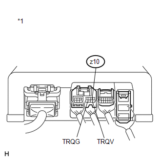
CHECK POWER STEERING ECU (TRQV VOLTAGE) |
(a) Turn the ignition switch to ON.
(b) Measure the voltage according to the value(s) in the table below.
Standard Voltage:
|
Tester Connection |
Switch Condition |
Specified Condition |
|---|---|---|
|
z10-6 (TRQV) - z10-8 (TRQG) |
Ignition switch ON |
4.5 to 5.5 V |
|
*1 |
Component with harness connected (Power Steering ECU) |
| NG | |
REPLACE POWER STEERING ECU |
|
|
3. |
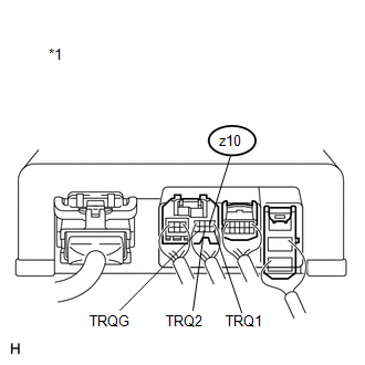
CHECK POWER STEERING ECU (TRQ1, TRQ2 VOLTAGE) |
|
(a) Start the engine. |
|
(b) Measure the voltage according to the value(s) in the table below.
Standard Voltage:
|
Tester Connection |
Condition |
Specified Condition |
|---|---|---|
|
z10-5 (TRQ1) - z10-8 (TRQG) |
The engine running, steering wheel not turned (without load). |
2.3 to 2.7 V |
|
The engine running, steering wheel turned to right with vehicle stopped. |
2.5 to 3.8 V |
|
|
The engine running, steering wheel turned to left with vehicle stopped. |
1.2 to 2.5 V |
|
|
z10-7 (TRQ2) - z10-8 (TRQG) |
The engine running, steering wheel not turned (without load). |
2.3 to 2.7 V |
|
The engine running, steering wheel turned to right with vehicle stopped. |
1.2 to 2.5 V |
|
|
The engine running, steering wheel turned to left with vehicle stopped. |
2.5 to 3.8 V |
(c) Under each condition, measure the voltage at terminals TRQ1 and TRQ2, and calculate the sum.
Standard Voltage:
|
Inspection Item |
Condition |
Specified Condition |
|---|---|---|
|
Sum of voltage between z10-5 (TRQ1) and z10-8 (TRQG) and voltage between z10-7 (TRQ2) and z10-8 (TRQG) |
The engine running, steering wheel not turned (without load). |
Between 4.75 V and 5.25 V |
|
The engine running, steering wheel turned to right with vehicle stopped. |
||
|
The engine running, steering wheel turned to left with vehicle stopped. |
|
*1 |
Component with harness connected (Power Steering ECU) |
| OK | |
REPLACE POWER STEERING ECU |
| NG | |
REPLACE STEERING COLUMN ASSEMBLY |
 Motor Circuit Malfunction (C1521,C1531-C1534,C1554)
DESCRIPTION
If the power steering ECU detects these DTCs, it will shut off the motor relay
circuit (built into the power steering ECU) and stop power assist. However, power
assist continues if DT ...
 Torque Sensor Zero Point Adjustment Undone (C1515,C1525)
DESCRIPTION
These DTCs do not indicate a malfunction. The power steering ECU stores these
DTCs when it determines that the rotation angle sensor value initialization and
torque sensor zero point ...
Other materials about Toyota Venza:
Open in Front Passenger Side Electrical Antenna Circuit (B27A2)
DESCRIPTION
The certification ECU (smart key ECU assembly) generates a request signal and
sends it to the door electrical key oscillator built into the front door outside
handle assembly (for front passenger side) at 0.25-second intervals. To detect a
k ...
Drive Belt
Components
COMPONENTS
ILLUSTRATION
On-vehicle Inspection
ON-VEHICLE INSPECTION
PROCEDURE
1. INSPECT V-RIBBED BELT
(a) Check the belt for wear, cracks or other signs of damage.
If any of the following defects is found, replace the V-r ...
Precaution
PRECAUTION
1. PRECAUTION FOR DISCONNECTING THE BATTERY CABLE
NOTICE:
When disconnecting the cable from the negative (-) battery terminal, initialize
the following systems after the terminal is reconnected.
System Name
See Procedure
...

0.1588