Toyota Venza: Removal
REMOVAL
CAUTION / NOTICE / HINT
HINT:
- Use the same procedure for the RH side and LH side.
- The procedure listed below is for the LH side.
PROCEDURE
1. REMOVE REAR WHEEL
2. SEPARATE REAR SPEED SENSOR
.gif)
3. REMOVE REAR AXLE SHAFT NUT
4. SEPARATE REAR DISC BRAKE CALIPER ASSEMBLY
5. REMOVE REAR DISC
6. REMOVE REAR AXLE HUB AND BEARING ASSEMBLY
7. SEPARATE NO. 3 PARKING BRAKE CABLE ASSEMBLY
8. REMOVE REAR STRUT ROD ASSEMBLY
9. REMOVE REAR AXLE CARRIER SUB-ASSEMBLY
|
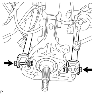
(a) Loosen the 2 bolts. NOTICE: Since stopper nuts are used, loosen the bolts. |
|
|
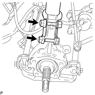
(b) Remove the 2 bolts and 2 nuts, and separate the rear shock absorber with coil spring (lower side) from the rear axle carrier sub-assembly. NOTICE:
|
|
|
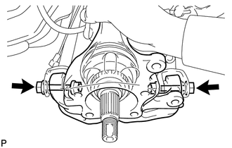
(c) Remove the 2 bolts, 2 nuts and rear axle carrier sub-assembly. NOTICE:
|
|
 Components
COMPONENTS
ILLUSTRATION
...
 Installation
INSTALLATION
CAUTION / NOTICE / HINT
HINT:
Use the same procedure for the RH side and LH side.
The procedure listed below is for the LH side.
PROCEDURE
1. INSTALL REAR AXLE CARR ...
Other materials about Toyota Venza:
Removal
REMOVAL
PROCEDURE
1. DISCONNECT CABLE FROM NEGATIVE BATTERY TERMINAL
NOTICE:
When disconnecting the cable, some systems need to be initialized after the cable
is reconnected (See page ).
2. REMOVE UPPER CONSOLE PANEL SUB-ASSEMBLY (w/o Seat Heater Syste ...
Inspection
INSPECTION
PROCEDURE
1. INSPECT FRONT DRIVE SHAFT ASSEMBLY
(a) Check whether the drive shaft dimensions are within the following
specifications.
Text in Illustration
*A
LH
*B
...
Problem Symptoms Table
PROBLEM SYMPTOMS TABLE
HINT:
Use the table below to help determine the cause of problem symptoms.
If multiple suspected areas are listed, the potential causes of the symptoms
are listed in order of probability in the "Suspected Area" ...

0.164