Toyota Venza: Vehicle Speed Sensor Malfunction (B2415)
DESCRIPTION
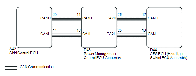
The AFS ECU (headlight swivel ECU assembly) receives signals indicating the front right wheel speed from the skid control ECU using CAN communication.
|
DTC No. |
DTC Detection Condition |
Trouble Area |
|---|---|---|
|
B2415 |
Malfunction in vehicle speed sensor |
|
WIRING DIAGRAM
CAUTION / NOTICE / HINT
NOTICE:
First perform the communication function inspections in How to Proceed with Troubleshooting to confirm that there are no CAN communication malfunctions before troubleshooting this symptom.
PROCEDURE
|
1. |
CHECK FOR DTC |
(a) Clear the DTCs (See page .gif) ).
).
(b) Check for DTCs (See page ).
OK:
DTC B2415 is not output.
| OK | .gif) |
USE SIMULATION METHOD TO CHECK |
|
.gif)
|
2. |
CHECK FOR DTC (ELECTRONICALLY CONTROLLED BRAKE SYSTEM) |
(a) Check for DTCs (See page ).
OK:
Electronically controlled brake system DTCs are not output.
| OK | |
REPLACE AFS ECU (HEADLIGHT SWIVEL ECU ASSEMBLY) |
| NG | |
GO TO ELECTRONICALLY CONTROLLED BRAKE SYSTEM |
 Height Control Sensor Malfunction (B2416)
DESCRIPTION
The DTC is stored when the headlight leveling ECU assembly detects malfunctions
in the rear height control sensor sub-assembly RH power source or rear height control
sensor sub-assemb ...
 Height Control Sensor Data Out of Range When Initializing (B2452)
DESCRIPTION
The headlight leveling ECU assembly stores this DTC if the sensor value received
from the height control sensor is out of range when performing initialization of
the headlight levelin ...
Other materials about Toyota Venza:
Precaution
PRECAUTION
CAUTION:
Replace any faulty seat belt components (outer belt, inner belt, bolts, nuts,
adjustable shoulder anchor, tether anchor hardware and other related parts). When
inspecting a vehicle that was in a collision, be sure to check all of the ...
Power Seat does not Return to Memorized Position
DESCRIPTION
When either the M1 or M2 switch is pressed, the outer mirror control ECU assembly
LH sends a switch signal to the main body ECU (driver side junction block assembly)
via CAN communication. Then, the main body ECU (driver side junction block as ...
Removal
REMOVAL
PROCEDURE
1. REMOVE REAR SEAT HEADREST ASSEMBLY
2. REMOVE REAR SEAT INNER TRACK BRACKET COVER
3. REMOVE REAR SEAT OUTER TRACK BRACKET COVER
4. DISCONNECT REAR SEAT NO. 2 RECLINING CONTROL CABLE SUB-ASSEMBLY
5. REMOVE REAR SEAT ASSEMBL ...

0.1255