Toyota Venza: Components
COMPONENTS
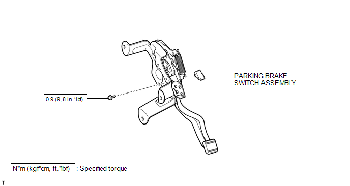
ILLUSTRATION
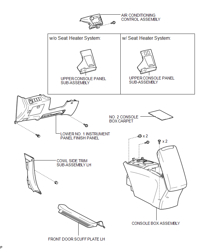
ILLUSTRATION
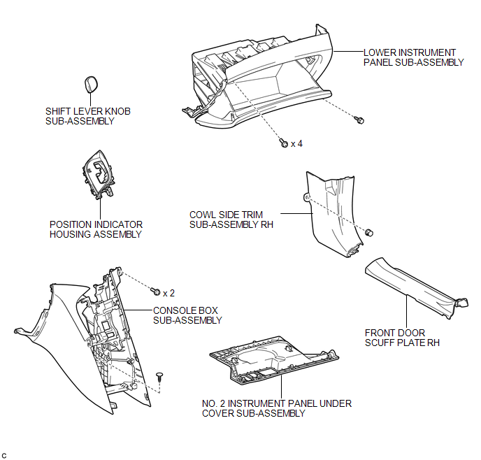
ILLUSTRATION
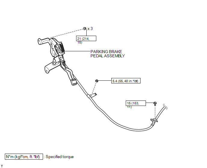
ILLUSTRATION

 Removal
REMOVAL
PROCEDURE
1. DISCONNECT CABLE FROM NEGATIVE BATTERY TERMINAL
CAUTION:
Wait at least 90 seconds after disconnecting the cable from the negative (-)
battery terminal to disable the SRS sys ...
Other materials about Toyota Venza:
Installation
INSTALLATION
PROCEDURE
1. TEMPORARILY TIGHTEN COMPRESSOR AND MAGNETIC CLUTCH
(a) Temporarily install the compressor and magnetic clutch and bracket
with the 4 bolts.
2. INSTALL COMPRESSOR AND MA ...
Disposal
DISPOSAL
PROCEDURE
1. DISPOSE OF FRONT SHOCK ABSORBER ASSEMBLY
(a) Position the front shock absorber assembly level with the piston
rod fully extended. Using a drill, make a hole in the cylinder between A
and B as shown in the illustratio ...
Power Management Control Ecu
Components
COMPONENTS
ILLUSTRATION
Removal
REMOVAL
PROCEDURE
1. REMOVE FRONT DOOR SCUFF PLATE RH
2. REMOVE COWL SIDE TRIM SUB-ASSEMBLY RH
3. REMOVE NO. 2 INSTRUMENT PANEL UNDER COVER SUB-ASSEMBLY
4. REMOVE LOWER INSTRUMENT PANEL SUB-ASS ...

0.1674