Toyota Venza: Initialization
INITIALIZATION
NOTICE:
Make sure that the front passenger seat is not occupied before performing the operation.
HINT:
Perform zero point calibration and sensitivity check if any of the following conditions occur:
- The occupant classification ECU is replaced.
- Accessories (seatback tray and seat cover, etc.) are installed.
- The front passenger seat is removed from the vehicle.
- The passenger airbag ON/OFF indicator ("OFF") comes on when the front passenger seat is not occupied.
- An occupant classification sensor collision detection DTC is output due to an accident or a collision.
1. ZERO POINT CALIBRATION
(a) Zero point calibration procedure
HINT:
Make sure that the zero point calibration has finished normally, and then perform sensitivity check.
(1) Check that all of the following conditions are met:
- The vehicle is parked on a level surface.
- No objects are placed on the front passenger seat.
- The front passenger seat belt buckle switch is off.
(2) Adjust the seat position according to the table below.
|
Adjustment Item |
Position |
|---|---|
|
Slide Direction |
Rearmost position |
|
Reclining Angle |
Upright position |
|
Headrest Height |
Lowest position |
(3) Turn the ignition switch off.
(4) Connect the Techstream to the DLC3.
(5) Turn the ignition switch to ON and turn the Techstream on.
(6) Enter the following menus: Body Electrical / Occupant Detection / Utility / Zero Point Calibration.
(7) Perform zero point calibration by following the prompts on the Techstream screen.
HINT:
- Refer to the Techstream operator's manual for further details.
- If zero point calibration does not complete, replace the front seat frame with adjuster assembly RH
OK:
"Zero Point Calibration is complete." is displayed.
2. SENSITIVITY CHECK
(a) Sensitivity check procedure
(1) Turn the ignition switch off.
(2) Connect the Techstream to the DLC3.
(3) Turn the ignition switch to ON and turn the Techstream on.
(4) Enter the following menus: Body Electrical / Occupant Detection / Utility / Sensitivity Check.
(5) Perform sensitivity check by following the prompts on the Techstream screen.
HINT:
Refer to the Techstream operator's manual for further details.
(6) Confirm that the initial sensor reading is within the specified range.
Standard:
-3.2 to 3.2 kg (-7.0 to 7.0 lb)
(7) Place a 30 kg (66.1 lb) weight (eg. a 30 kg (66.1 lb) of lead mass) onto the front passenger seat.
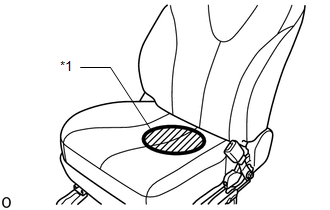
NOTICE:
- Do not allow the weight to come into contact with the seatback when placing it on the seat cushion.
- Place the weight in the area shown in the illustration.
|
*1 |
Weight Position |
(8) Confirm that sensitivity is within the specified range.
Standard:
27 to 33 kg (59.5 to 72.8 lb)
HINT:
- When performing sensitivity check, use a solid metal weight (the check result may not appear properly if a liquid weight made from liquid is used).
- If sensitivity deviates from the specified range, retighten the bolts of the front passenger seat without deforming the seat rail. After performing this procedure, if sensitivity is not within the specified range, replace the front seat frame with adjuster assembly RH.
 System Description
SYSTEM DESCRIPTION
1. DESCRIPTION OF OCCUPANT CLASSIFICATION SYSTEM
(a) GENERAL DESCRIPTION
(1) In the occupant classification system, the occupant classification ECU calculates
the weight of the ...
 Problem Symptoms Table
PROBLEM SYMPTOMS TABLE
HINT:
Use the table below to help determine the cause of problem symptoms.
If multiple suspected areas are listed, the potential causes of the symptoms
are lis ...
Other materials about Toyota Venza:
Setting up the displays
Press the “SETUP” button while the
vehicle is stopped.
The “Custom Settings” screen is displayed on the multi-information display.
If left idle for approximately 10 seconds, the display will revert to the previous
screen.
Select “Display / ...
How To Use This Manual
General Information
GENERAL INFORMATION
1. GENERAL DESCRIPTION
(a) This manual is written in accordance with SAE J2008.
(b) Repair operations can be separated mainly into the following 3 processes:
(1) Diagnosis
(2) Removing / Installing, Replacing, Di ...
IG Power Source Circuit
DESCRIPTION
The main power source is supplied to the A/C amplifier when the ignition switch
is ON.
The power source is used for operating the A/C amplifier and servo motor, etc.
WIRING DIAGRAM
CAUTION / NOTICE / HINT
NOTICE:
Inspect the fuses for cir ...

0.1778