Toyota Venza: Removal
REMOVAL
PROCEDURE
1. REMOVE PARKING BRAKE PEDAL ASSEMBLY
HINT:
Refer to the instructions for Removal of the parking brake pedal assembly (See
page .gif) ).
).
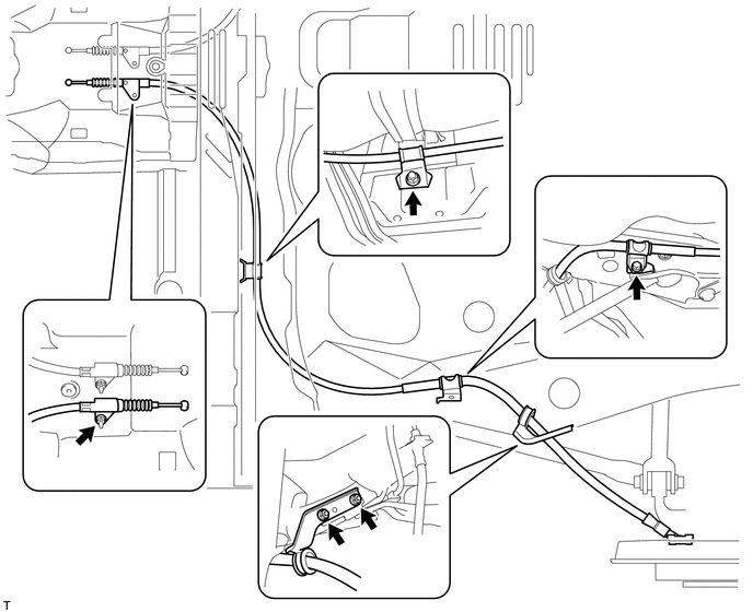
2. REMOVE NO. 1 PARKING BRAKE CABLE ASSEMBLY
|
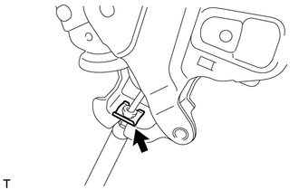
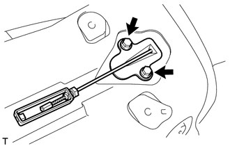
(a) Remove the clip. |
|
|
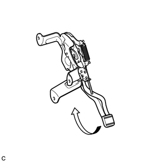
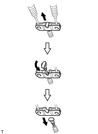
(b) Depress the parking brake pedal. |
|
|
(c) Pull up the parking brake pedal claw and remove the No. 1 parking brake cable assembly from the parking brake pedal assembly. |
|
3. REMOVE REAR WHEEL
4. REMOVE NO. 4 PARKING BRAKE CABLE ASSEMBLY
|
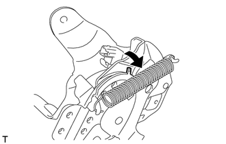
(a) Slide the rubber boot as shown in the illustration. |
|
|
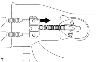
(b) Separate the No. 4 parking brake cable assembly from the parking brake equalizer as shown in the illustration. |
|
|
(c) Remove the 2 bolts and No. 4 parking brake cable assembly. |
|
5. REMOVE PARKING BRAKE EQUALIZER
|
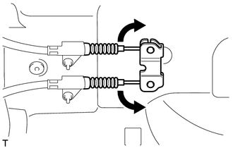
(a) Move the No. 2 parking brake cable assembly and No. 3 parking brake cable assembly as shown in the illustration to remove the parking brake equalizer. |
|
6. REMOVE NO. 2 PARKING BRAKE SHOE ASSEMBLY WITH PARKING BRAKE SHOE LEVER
HINT:
Refer to the instructions for Removal of the No. 2 parking brake shoe assembly
with parking brake shoe lever (See page ).
7. REMOVE NO. 3 PARKING BRAKE CABLE ASSEMBLY
|
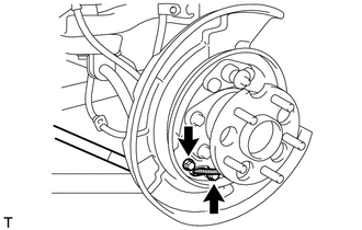
(a) Remove the 2 bolts and separate the No. 3 parking brake cable assembly from the backing plate. |
|
(b) Remove the bolt, 4 nuts and the No. 3 parking brake cable assembly.
8. REMOVE NO. 2 PARKING BRAKE CABLE ASSEMBLY
HINT:
Use the same procedure as for the No. 3 parking brake cable assembly.
 Components
COMPONENTS
ILLUSTRATION
ILLUSTRATION
ILLUSTRATION
...
 Installation
INSTALLATION
PROCEDURE
1. INSTALL NO. 3 PARKING BRAKE CABLE ASSEMBLY
(a) Install the No. 3 parking brake cable assembly with the bolt and 4 nuts.
Torque:
Nut (A) :
5.4 N·m {55 kgf·cm, 48 i ...
Other materials about Toyota Venza:
Brake Switch "A" Circuit (P0571)
DESCRIPTION
When the brake pedal is depressed, the stop light switch assembly sends a signal
to the ECM. When the ECM receives this signal, it cancels the cruise control. The
fail-safe function operates to enable normal driving even if there is a malfunct ...
Speed Signal Malfunction (B15C2)
DESCRIPTION
The navigation receiver assembly receives a vehicle speed signal from the combination
meter assembly and information from the navigation antenna assembly, and then adjusts
the vehicle position.
The navigation receiver assembly stores this DTC ...
ECU Power Source Circuit
DESCRIPTION
This circuit provides power for main body ECU (driver side junction block assembly)
operation.
WIRING DIAGRAM
PROCEDURE
1.
CHECK DRIVER SIDE JUNCTION BLOCK ASSEMBLY (MAIN BODY ECU (POWER SOURCE))
...

0.1179